Figure 2. h2tu-c span powering diagram – ADTRAN AHDSL2 User Manual
Page 3
61221002L2-5B
3
2. APPLICATIONS
The ADTRAN HDSL2 system provides a
cost-effective alternative for deploying T1 service
over metallic cable pairs. In contrast with traditional
T1 service equipment, ADTRAN HDSL2 can be
successfully deployed over one unconditioned,
nonloaded, bridged-tapped copper pair CSA loop (see
Deployment Guidelines
, Section 4).
Litespan HDSL2 deployment is typically made from a
Litespan 2000, Litespan 2012, or Litespan ONU
channel bank assembly. Figure 3 shows possible
ADTRAN HDSL2 deployments from a Litespan
channel bank assembly. ADTRAN HDSL2 systems
can be deployed quickly without the use of expensive
T1 repeater equipment on standard CSA loops while
using the existing massive copper-fed twisted line
pairs in use by the industry.
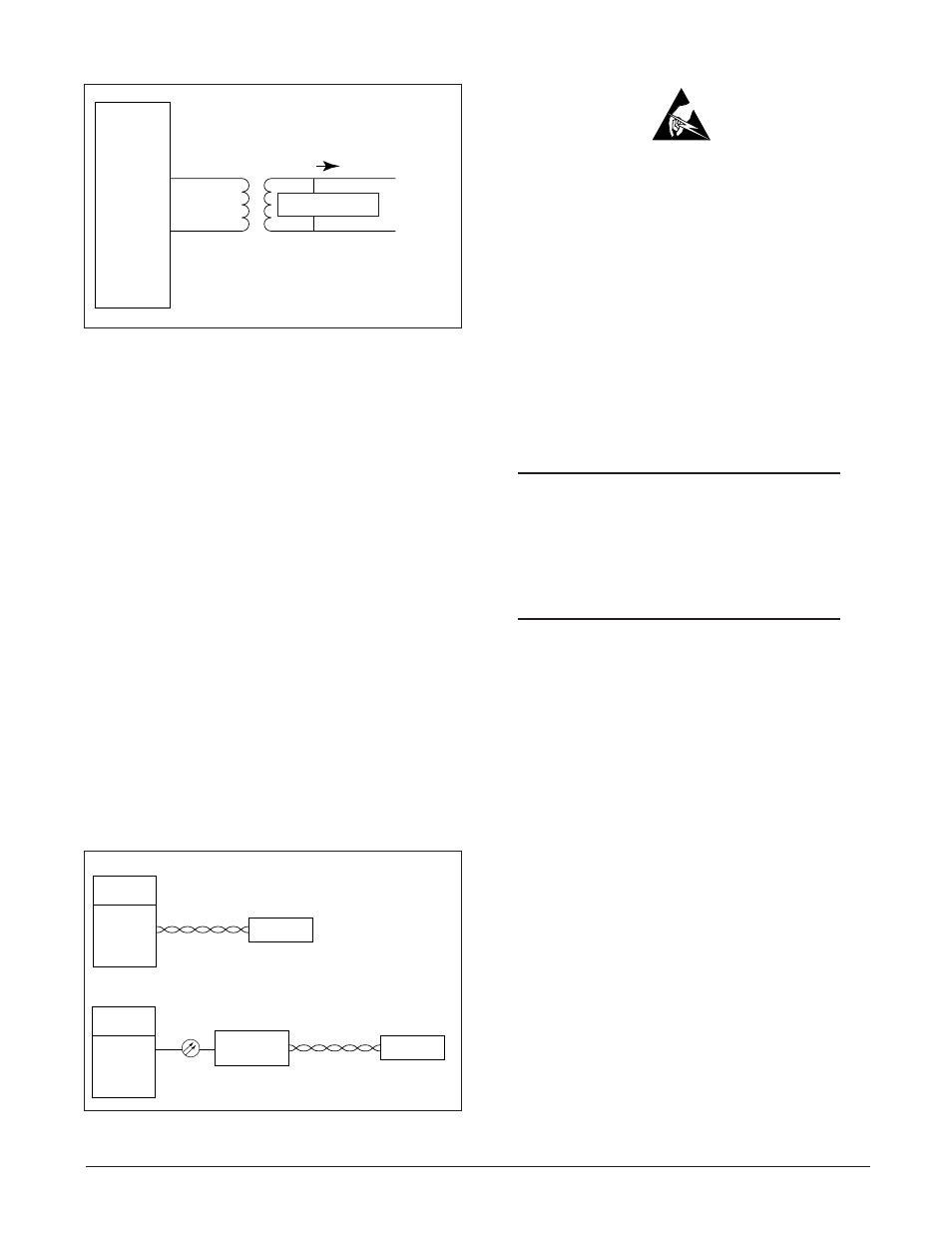
ADTRAN uses negative ground-referenced span
powering voltage (–190 VDC) on HDSL2 loop.
H2TU-R span powering can be disabled to allow
locally powered H2TU-R applications, if desired.
3. INSTALLATION
C A U T I O N
C A U T I O N !
SUBJECT TO ELECTROSTATIC DAMAGE
OR DECREASE IN RELIABILITY.
HANDLING PRECAUTIONS REQUIRED.
After unpacking the unit, inspect it for damage. If
damage is noted, file a claim with the carrier, then
contact ADTRAN. Refer to Warranty and Customer
Service.
The Litespan H2TU-C plugs directly into a Litespan
channel bank assembly channel unit slot. Litespan
system software must be version 11.0.0 or higher.
The tip and ring connections from the H2TU-C to the
shelf are made through the following card edge pins:
• Narrowband Tip – Pin A3
• Narrowband Ring – Pin A4
CAUTION
Do not deploy the Litespan H2TU-C into any
Litespan channel bank assembly slot that has
ADSL Power Distribution Fuse and Alarm
(PDFA) connections to the wideband pairs of
the channel bank assembly.
This unit supports narrowband cabling only on the
Litespan RT shelf. For more information regarding
cabling, reference Alcatel document Mechanical Unit
Descriptions, OSP 363-405-270.
Upon insertion of an H2TU-C into an unprovisioned
slot, the STAT LED should turn red immediately.
The STAT LED will remain red until the Litespan
bank recognizes the insertion of the card and
downloads the AHDSL2 channel unit type code into
the line card. Typically, the STAT LED will remain
red for approximately 15 to 20 seconds (time may
vary). Approximately 3 to 4 seconds after the STAT
LED turns off, the HLOS LED will turn red and
remain so until the H2TU-C and H2TU-R units
synchronize with each other over the HDSL2 loop.
The STAT LED will turn green after synchronization
of the HDSL2 loop.
Figure 3. Deployment from a Litespan
Channel Bank
Common
Control
Channel Bank
Assembly with
a Litespan
H2TU-C
Installed
HDSL2 Unit
Remote End
HDSL2 Loop Pair
Litespan 2000 or 2012 System with Litespan H2TU-C deployment
Common
Control
High-Density
Fiber Bank
ONU-96 with
an installed
Litespan H2TU-C
OLNK
HDT
Typical Starspan System
HDSL2 Unit
Remote End
HDSL2 Loop Pair
Figure 2. H2TU-C Span Powering Diagram
HDSL2
TIP (
+)
RING (
−)
SPAN POWER
−190V
SPAN CURRENT