Relay connections, Input/output (i/o) connections and wiring – AMX NetLinx Integrated Controllers NI-3000 User Manual
Page 31
Connections and Wiring
25
NetLinx Integrated Controllers
A metal commoning strip is supplied with each Integrated Controller to connect multiple
relays.
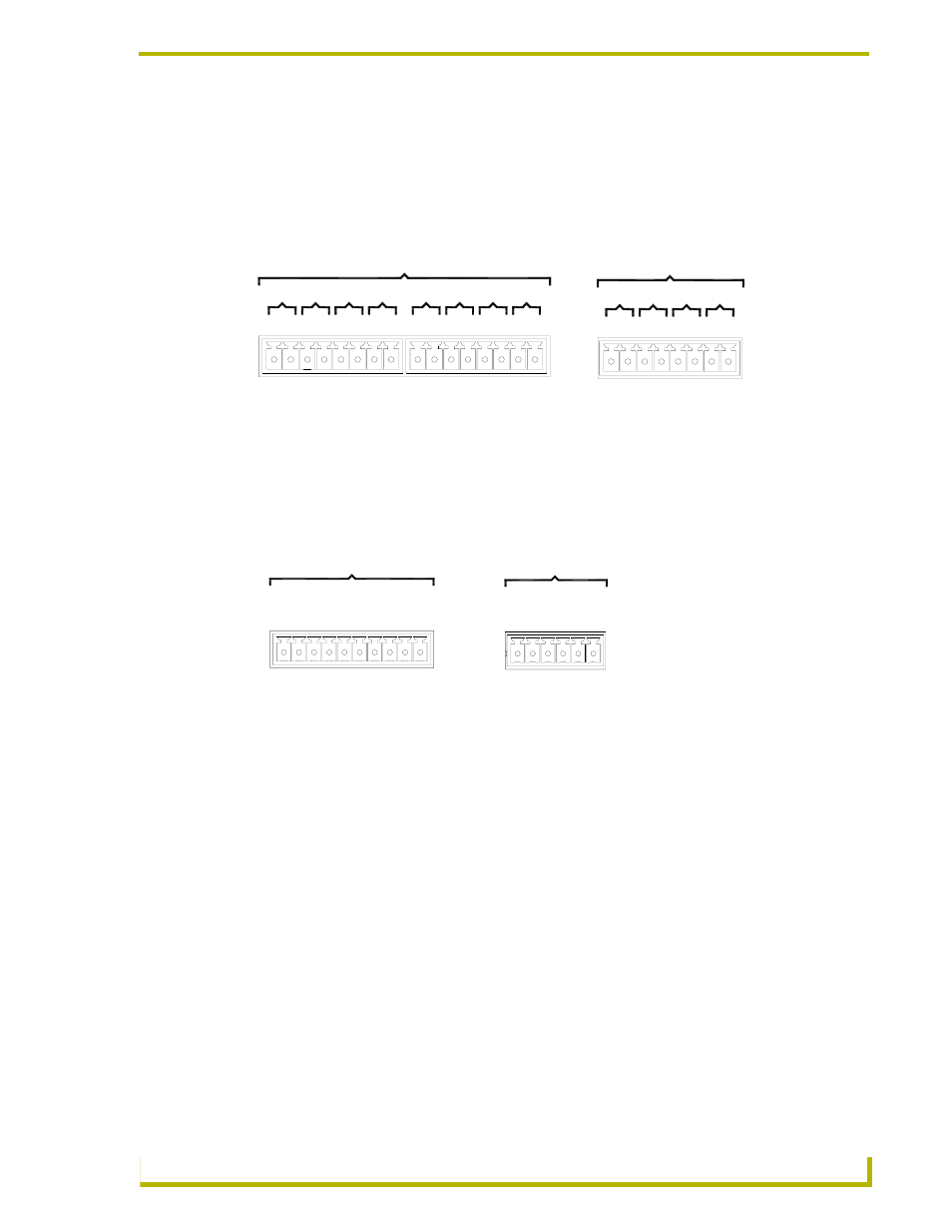
Relay connections
Use A for common and B for output (FIG. 14). Each relay is isolated and normally open. A metal
connector strip is also provided to common multiple relays.
Input/Output (I/O) Connections and Wiring
The I/O port responds to either switch closures, voltage level (high/low) changes, or can be used for
logic-level outputs.
You can connect up to eight devices to the I/O connectors on the NI-4000/3000 (four on the
NI-2000) (FIG. 15). A contact closure between GND and an I/O port is detected as a Push. When
used for voltage inputs, the I/O port detects a low (0-1.5 VDC) as a Push, and a high (3.5-5 VDC)
signal as a Release. When used for outputs, the I/O port acts as a switch to GND and is rated at 200
mA @ 12 VDC. The PWR pin (+12 VDC @ 200 mA) is designed as a power output for the PCS2
or VSS2 (or equivalent). The GND connector is a common ground and is shared by all I/O ports.
The following table lists the wiring specifications for the I/O connectors.
+12V - 12 VDC power output for PCS Power Current Sensors, VSS2 Video Sync
Sensors, or similar I/O-type equipment
I/O 1 - 8 - Up to 8 I/O ports (NI-4000/3000) and up to 4 I/O ports (NI-2000)
(see table below)
GND - Common ground shared with I/O ports 1 - 8 (refer to the following chart)
FIG. 14 RELAY connector (male) (NI-4000/3000/2000)
FIG. 15 INPUT/OUTPUT connector (male)
2
4
A
B
3
B
A
B
1
A
A B
RELAYS (Port 4)
RELAYS (Port 8)
B
6
A
8
B
B
B
7
A
5
B
A
A
4
B A
A
3
A
2
B
1
A
B
NI-4000/NI-3000 relay connector
configuration (Port 8)
NI-2000 relay connector
configuration (Port 4)
I / O (Port 17)
4
+12V
7
8
6 5
GN
D
2
3
1
I / O (Port 9)
4
+1
2V
2
3
1
GND
NI-4000/NI-3000 I/O connector
configuration (Port 17)
NI-2000 I/O connector
configuration (Port 9)