Using the configuration dip switch, Modes and front panel led blink patterns, Wiring guidelines – AMX NetLinx Integrated Controllers NI-3000 User Manual
Page 24
Connections and Wiring
18
NetLinx Integrated Controllers
Using the Configuration DIP switch
1.
Disconnect the power supply from the 2-pin PWR (green) connector on the rear of the NetLinx
Integrated Controller.
2.
Set DIP switch positions according to the information listed in the Baud Rate Settings on the
Configuration DIP Switch and PRD Mode Settings tables.
3.
Reconnect the 12 VDC power supply to the 2-pin 3.5 mm mini-Phoenix PWR connector.
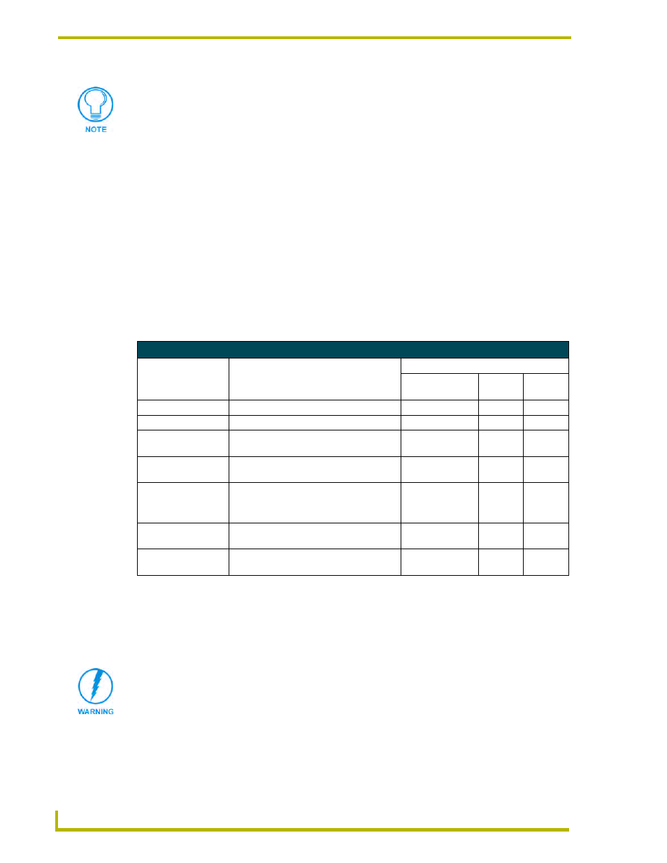
Modes and Front Panel LED Blink Patterns
The following table lists the modes and blink patterns for the front panel LEDs associated with
each mode. These patterns are not evident until after the unit is powered.
Wiring Guidelines
The Integrated Controllers require 12 VDC power from a NetLinx Power Supply to operate
properly (this supply is unit dependent). The Integrated Controller connects to the power supply via
a 2-pin 3.5 mm mini-Phoenix connector.
Think of the PRD Mode (On) equating to a PC’s SAFE Mode setting. This mode
allows a user to continue powering a unit, update the firmware, and download a new
program while circumventing any problems with a currently downloaded program.
Power must be cycled to the unit after activating/deactivating this mode on the
Program Port DIP switch #1.
Modes and LED Blink Patterns
LEDs and Blink Patterns
Mode
Description
STATUS
(green)
OUTPUT
(red)
INPUT
(yellow)
OS Start
Starting the operating system (OS).
On
On
On
Boot
On-board Master is booting.
On
Off
On
Contacting DHCP
server
On-board Master is contacting a DHCP
server for IP configuration information.
On
Off
Fast Blink
Unknown DHCP
server
On-board Master could not find the
DHCP server.
Fast Blink
Off
Off
Downloading Boot
firmware
Downloading Boot firmware to the
Master’s on-board flash memory.
Do not cycle power during this process!
Fast Blink
Fast Blink Fast Blink
No program running
There is no program loaded, or the
program is disabled.
On
Normal
Normal
Normal
On-board Master is functioning normally.
1 blink per second
Indicates
activity
Indicates
activity
This unit should only have one source of incoming power. Using more than one
source of power to the Controller can result in damage to the internal components
and a possible burn out.
Apply power to the unit only after installation is complete.