General information, Maintenance, Cathodic protection – A.O. Smith 400A User Manual
Page 27: Precautions, Power burner, High limit, High altitude installations, General, Maintenance schedule
7
WARNING
UNDER NO CIRCUMSTANCES SHOULD THE INPUT EXCEED
THE RATE SHOWN ON THE HEATER RATING PLATE.
OVERFIRING COULD RESULT IN DAMAGE OR SOOTING OF
THE HEATER.
CATHODIC PROTECTION
CAUTION
HYDROGEN GAS CAN BE PRODUCED IN A HOT WATER
SYSTEM SERVED BY THIS HEATER THAT HAS NOT BEEN
USED FOR A LONG PERIOD OF TIME (GENERALLY TWO
WEEKS OR MORE). HYDROGEN GAS IS EXTREMELY
FLAMMABLE.
To reduce the risk of injury under these conditions,
it is recommended that a hot water faucet be opened for several
minutes before using any electrical appliance connected to the
hot water system. If hydrogen is present, there will probably be an
unusual sound such as air escaping through the pipe as the water
begins to flow. There should be no smoking or open flame near the
faucet at the time it is open.
PRECAUTIONS
IF THE UNIT IS EXPOSED TO OR EXHIBITS THE FOLLOWING,
DO NOT OPERATE HEATER UNTIL ALL CORRECTIVE STEPS
HAVE BEEN MADE BY A QUALIFIED SERVICEMAN.
. FLOODING TO OR ABOVE THE LEVEL OF THE BURNER OR
CONTROLS
. EXTERNAL DAMAGE
3. FIRING WITHOUT WATER
4. SOOTING
NEVER OPERATE THE HEATER WITHOUT FIRST BEING
CERTAIN IT IS FILLED WITH WATER AND A TEMPERATURE
AND PRESSURE RELIEF VALVE IS INSTALLED IN THE RELIEF
VALVE OPENING OF THE HEATER.
SHOULD OVERHEATING OCCUR OR THE GAS SUPPLY FAIL TO
SHUT OFF, TURN OFF THE MANUAL GAS CONTROL VALVE TO
THE APPLIANCE.
GENERAL INFORMATION
POWER BURNER
The initial start-up procedure of the unit is provided on page 25.
The sequence of operation of the unit is provided on page 20.
It is important to note that the controller has a reset button on the
control box, Figure 1. The reset button is a safety device and would
not normally be used.
HIGH LIMIT
The high limit (not adjustable) is factory set to cutout at
202°F (94°C). The controller will not be reset until water temperature
drops to below 140°F (61°C).
HIGH ALTITUDE INSTALLATIONS
WARNING
BTH HEATERS ARE CERTIFIED FOR USE WITHOUT
MODIFICATION FOR ALTITUDES UP TO 10,000 FEET.
INSTALLATIONS ABOVE 10,000 FEET MAY REQUIRE
REPLACEMENT OF THE BURNER ORIFICE. CALL THE
TECHNICAL INFORMATION CENTER AT (800) 527-1953 FOR
REQUIREMENTS.
Some gas utility companies derate their gas for altitude, making it
unnecessary to install high altitude orifices. Call the local gas or
utility company to verify BTU content.
Due to the input rating reduction at high altitudes, the output rating
of the appliance is also reduced and should be compensated for in
the sizing of the equipment for applications.
MAINTENANCE
GENERAL
KEEP APPLIANCE AREA CLEAR AND FREE FROM
COMBUSTIBLE MATERIALS, GASOLINE AND OTHER
FLAMMABLE VAPORS AND LIQUIDS. (SEE WARNING ON PAGE
6, LOCATING THE HEATER).
Water heater maintenance includes periodic tank flushing
and cleaning, and removal of lime scale. The unit should be
inspected and adjusted to maintain proper combustion. Refer to
the following table. A periodic inspection of the venting system
should be made. Where used, the water circulating pump should
be oiled.
MAINTENANCE SCHEDULE
Following are the instructions for performing some of the
recommended maintenance. Unit inspection and adjustment should
be performed by a competent technician.
NOTE: UN•LIME is not available in Canada. Please call Customer
Service at 1-800-265-8520 for approved alternatives.
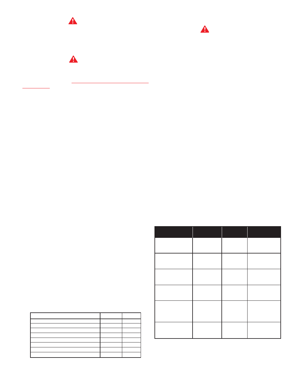
TABLE 4.
GAS SUPPLY SPECIFICATIONS Nat. Gas LP Gas
Max. Gas Supply Pressure W.C.
11.00
14.00
Max. Gas Supply Pressure kPa
2.74
3.49
Nominal Gas Supply Pressure W.C.
7.00
11.00
Nominal Gas Supply Pressure kPa
1.74
2.74
Minimum Gas Supply Pressure W.C.*
5.20
11.0
Minimum Gas Supply Pressure kPa*
1.54
2.74
Manifold Gas Supply Pressure W.C.
4.00
10.0
Manifold Gas Supply Pressure kPa
1.25
2.49
* Minimum pressure for purposes of rate adjustment
(1) If furnished with oiling provision.
COMPONENT
OPERATION
INTERVAL
REQUIRED
Tank
Sediment
Monthly
Flushing
Removal
Tank
Lime Scale
Semi
UN-LIME
®
Removal
Annually
Delimer
Powered Anode
Inspect
Semi
System
Annually
Relief Valve
Inspect
Semi
Annually
Clean Inlet
Blower
Screen and
As Required
Soft Brush
Blower Wheel
Vent System
Inspect
Every 3
Joints should
Months
be sealed