A.J. Antunes & Co SML 8221210034 User Manual
Sml installation information, Sml switches, Dimensions
1-630-784-1000 Fax: 630-784-1651
Page 1 of 4
P/N 1011084 06/10
1-800-253-2991
A. J. ANTUNES & CO. www.ajantunes.com 180 Kehoe Blvd., Carol Stream, Illinois 60188
SML Switches
You are installing one of the finest switches of its type on
the market. You will find this switch has many superior
features that ensure dependable, accurate, long life oper-
ation. This switch is highly sensitive and fully approved. It
is UL and CSA listed and has FM approval (optional).
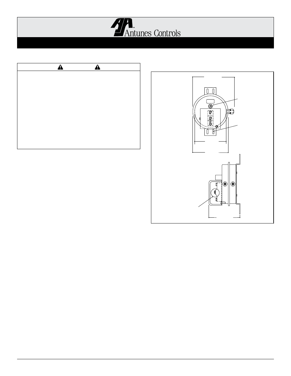
Dimensions
IMPORTANT
Please read these instructions carefully to assure
correct installation. This equipment must be
installed only by a licensed electrician who is
experienced with combustion safeguard control
systems and understands the functions of inter-
locking switches, such as gas pressure switches.
Prior to being put into operation in conjunction
with the combustion safeguard systems, all
switches should be tested for proper range setting
and proper wiring. Check piping connections and
switch house for leaks with a soap bubble test. All
exhaust fans and blowers should be inspected and
checked for proper rotation prior to starting up.
SML Installation Information
Specifications
Electrical Ratings: 10A @ 125 VAC, 8A @ 250 VAC, 7A
@ 277 VAC, 1/8 HP @ 125 VAC, 1/4 HP @250 VAC
Pilot Duty, 125 VA @ 125/277 VAC
Max. Surge Pressure: 20” W.C.
Max. Ambient Operating Temperature: 170°F (77°C)
Min. Ambient Operating Temperature: -40°F (-40°C)
Shipping Weight: 1 lbs. (.45 kg)
Optional Fittings:
1/4” Barb
1/4” Tube
1/4” Compression
Option: Neon Light Indicator
NOTE: Location of fittings and types of fittings may vary
from unit to unit.
Range Adjustment
All settings are made with the diaphragm in a vertical
position. The switch is shipped with the adjustment at
minimum .05” W. C.
To adjust, turn adjusting screw with screwdriver. To
increase pressure setting, turn adjustment screw in a
clockwise direction. To decrease pressure setting, turn
adjusting screw up in a counterclockwise direction.
If adjusting screw is removed, apply a non-hardening
pipe compound to the threads before replacing. Check for
leaks with a soap bubble test using maximum 20” W.C.
Installation
Models may be mounted in the horizontal or vertical posi-
tion. All switches are tested at the factory in a vertical
position. Mounting diaphragm in vertical position is the
preferred method.
If mounting in horizontal position, the micro switch must
be on top. When mounted in this position, the minimum
sensitivity may be higher than that specified.
Standard mounting
bracket is shown.
For other mounting
arrangements,
contact factory.
5 5/32”
(131 mm)
Standpipe with
adjusting
screw
Mounting holes
for #8 screws
1/2” Conduit
Knockout
4 9/16”
(116 mm)
4 1/16”
(103 mm)
3 5/16”
(135 mm)
NOTE: Dimensions
are for reference only.