A.J. Antunes & Co TFH 8503130044 User Manual
Tfh installation information, Dimensions panel cutout, Specifications
A. J. ANTUNES & CO. www.ajantunes.com 180 Kehoe Blvd., Carol Stream, Illinois 60188
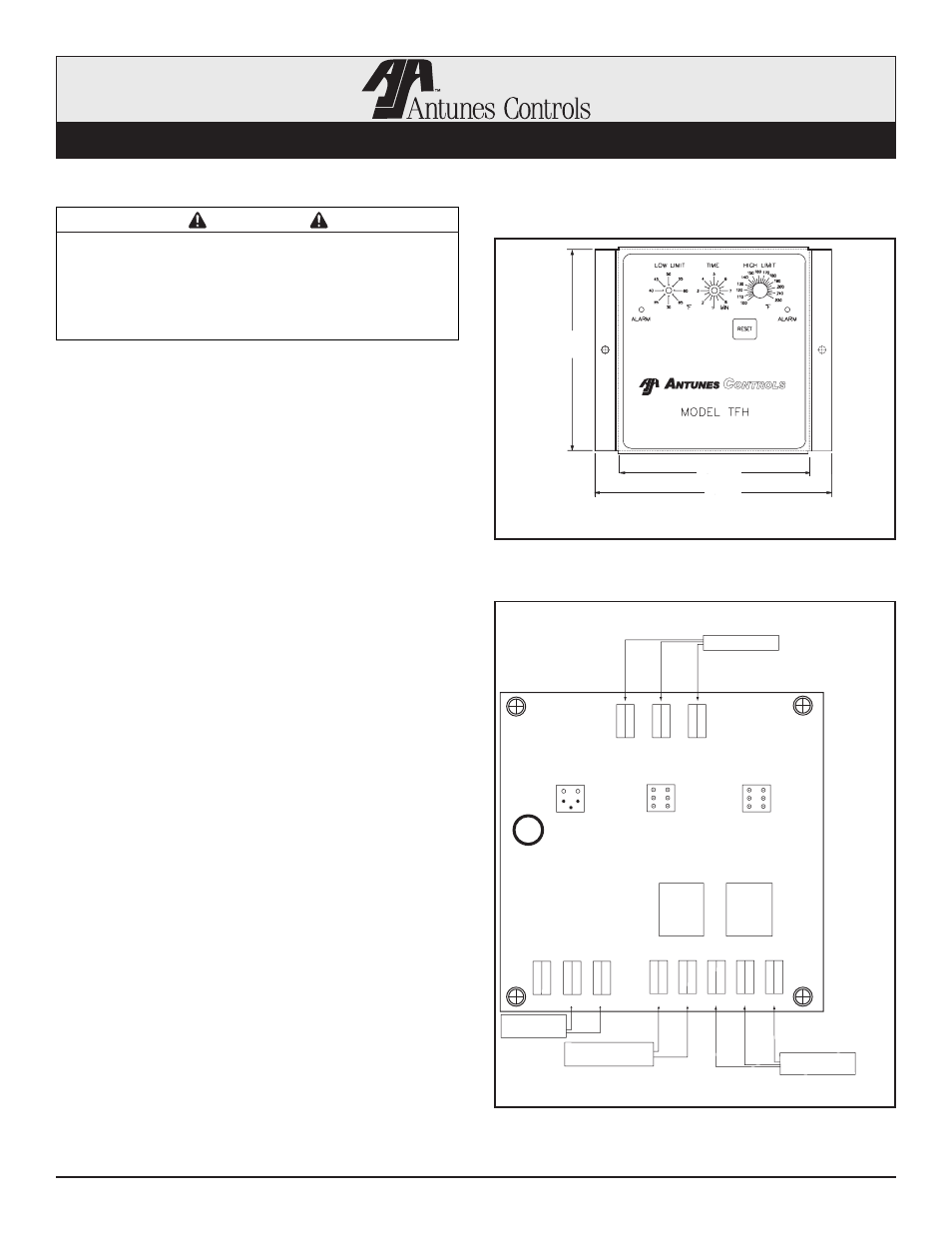
Dimensions
Panel Cutout
IMPORTANT
Please read these instructions carefully to assure
correct installation. This equipment must be
installed by a licensed electrician. Prior to being
put into operation, check all wiring and function of
the unit.
TFH Installation Information
Specifications
Sensor Type: 100K Thermistor (Dual) - Length (15 ft.)
Other lengths available upon request.
Accuracy: +/-3ºF of Setpoint
Power Input: 24 VAC, 120 VAC
Control Operation: Low Limit - Closes on Rise
High Limit - Opens on Rise
Output Ratings:
Low Limit - 8 Amp S.P.D.T. Relay Max. @ 240 VAC Max.
High Limit - 8 Amp S.P.S.T. Relay Max. @ 240 VAC Max.
(Resistive Load)
Adjustable Time Delay Range: 1–8.5 Minutes
Adjustable Temperature Range: Low Limit: 30ºF to 65ºF
High Limit: 100ºF to 220ºF
Ambient Operating Temperature: -30ºF to 140ºF
(-35ºF
to 60ºC)
Connections: 1/4” Quick Connects,
6” Wire Leads (Optional)
Package: Aluminum “C” Bracket - 5.1”L x 5.9”W x 3.1”D
(shown) Full Enclosure w/conduit knockout (optional)
Shipping Weight: 2 lbs. (.9 kg)
Connections
Thermistor Input: T1, T2 & T3 (100K ohm @ 25°C)
Power Input: T4 & T5 (24-120 VAC)
Low Limit Relay: T8 (N.O.), T9 (COM) & T10 (N.C.)
High Limit Relay: T6 (N.O.), T7 (COM)
Installation Note: For optimum accuracy, the sensor
must be mounted with a minimum of two feet of cable at
the sensor lug end being exposed to the same tempera-
ture as the sensor lug.
1-630-784-1000 Fax: 630-784-1651
Page 1 of 4
P/N 1011095 06/10
1-800-253-2991
5”
(127 mm)
4.7”
(119 mm)
5.87”
(149 mm)
NOTE: Dimensions are for reference only.
T1
T3
T2
T11 T5
T7
T6
T8
T4
T10
T9
R6
DS2
DS1
K1
HI
K2
LO
Sensor Input
Red
White
Blac
k
GND
COM
N.O.
N.O.
VAC
N.C.
COM
System Shutdown
Time-out Contacts
System Shutdown
Over-Temp. Contacts
Input Power
(24 VAC)