Allied Telesis AT-MC1005/4 User Manual
Page 23
AT-MC1004 and AT-MC1005/x Series Installation Guide
13
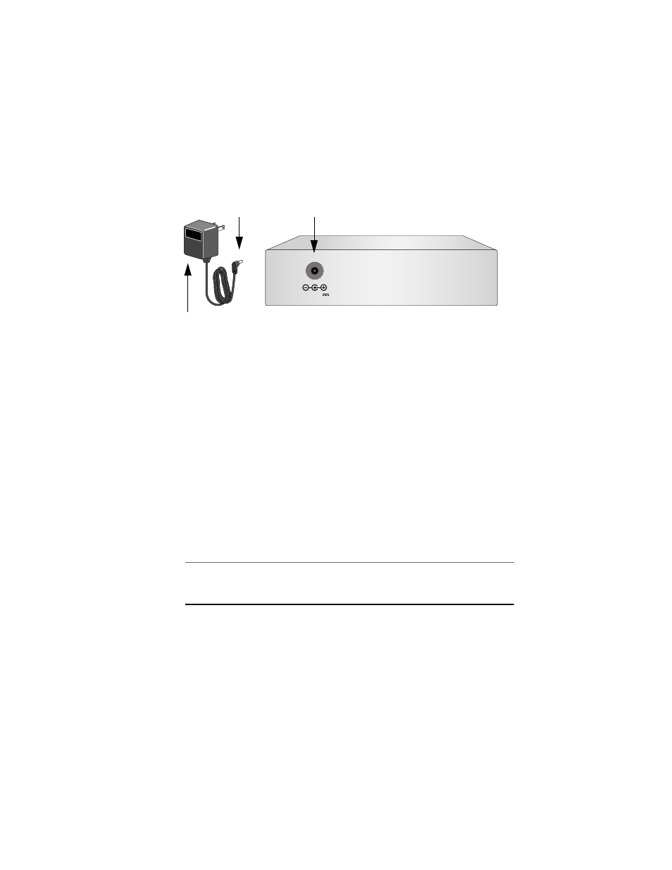
5.
Plug the AC/DC power adapter into an appropriate AC power outlet and
insert the power plug into the DC receptacle located on the back of the
unit. This step does not apply if you installed the unit in an
AT-MCR12 chassis.
Figure 7 DC Connector
6.
Verify that the PWR LED is green. If the LED is OFF, refer to
“Troubleshooting” on page 15 for instructions.
7.
Remove the dust cover from the fiber optic port and connect the data
cable. Make sure that the media converter’s receiver port (RX) is
connected to the end-node’s transmitter port (TX) and that the media
converter’s transmitter port (TX) is connected to the end-node’s receiver
port (RX).
8.
Connect the twisted pair cable to the twisted pair port.
9.
Power ON the end-nodes.
10. Check that LNK LEDs on both ports of the media converter are green. If
the LEDs are OFF, refer to “Troubleshooting” on page 15.
Note
End-nodes used with the media converter must be able to operate at
1000 Mbps in full-duplex mode.
The media converter is now ready for use.
12 V D C
DC Receptacle
Back of Media Converter
Power Plug
AC/DC Power Adapter