Allied Telesis AR300 SERIES ROUTER User Manual
Page 11
A R 3 0 0 R O U T E R Q U I C K S T A R T G U I D E
11
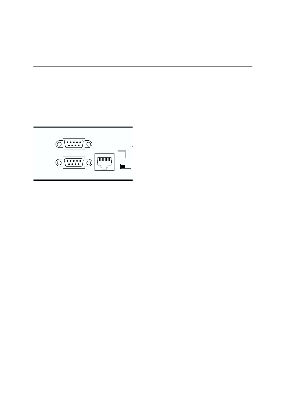
of the router. Models AT-AR300(S), AT-AR300L(S) and
AT-AR310(S) have DB9 female connectors. Models
AT-AR300(U), AT-AR300L(U), AT-AR310(U), AT-AR350,
AT-AR370(S), AT-AR370(U), AT-AR390 and AT-AR395 have
DB9 male connectors.
Note: If you wish to make your own cable, see the AR Router
Hardware Reference for a detailed description of how to wire a
terminal or modem cable.
50
ETHERNET 0
HUB
PC
MDX
PORT 1 (RS232)
PORT 0 (RS232)
Connect the terminal or modem to one of the asynchronous ports (Port 0 or Port 1)
on the rear panel of the AR300 Series router using an approved cable. Some models
have only one asynchronous port (Port 0).
2 Check that the terminal or modem’s communication
settings match the settings of the asynchronous port. By default,
asynchronous ports on the AR300 router are set to 9600 baud,
8 data bits, 1 stop bit, no parity and hardware flow control.
Refer to the user manual supplied with the terminal or modem
for details of how to change the communications settings for
the terminal or modem.
If the terminal or modem is to be used with communications
settings other than the router’s default settings, the
asynchronous port must be configured to match the terminal
or modem settings using the SET PORT command. If a modem
is being connected, the CDCONTROL parameter must be set
to “CONNECT” and the FLOW parameter must be set to
“HARDWARE”. See the router’s online help or the AR Series
Router Software Reference for more information.
3 If a modem is being connected, the router must be
configured to make and/or accept calls via the modem using an
Asynchronous Call Control (ACC) call. An ACC call definition is
created using the ADD ACC CALL command. See the router’s
online help or the AR Series Router Software Reference for more
information.