Connecting to a leased line circuit, Connecting a terminal or modem – Allied Telesis AR300 SERIES ROUTER User Manual
Page 10
10
A R 3 0 0 R O U T E R Q U I C K S T A R T G U I D E
75
Ω Tx
75
Ω Rx
PRI 0
120
Ω
120
Ω
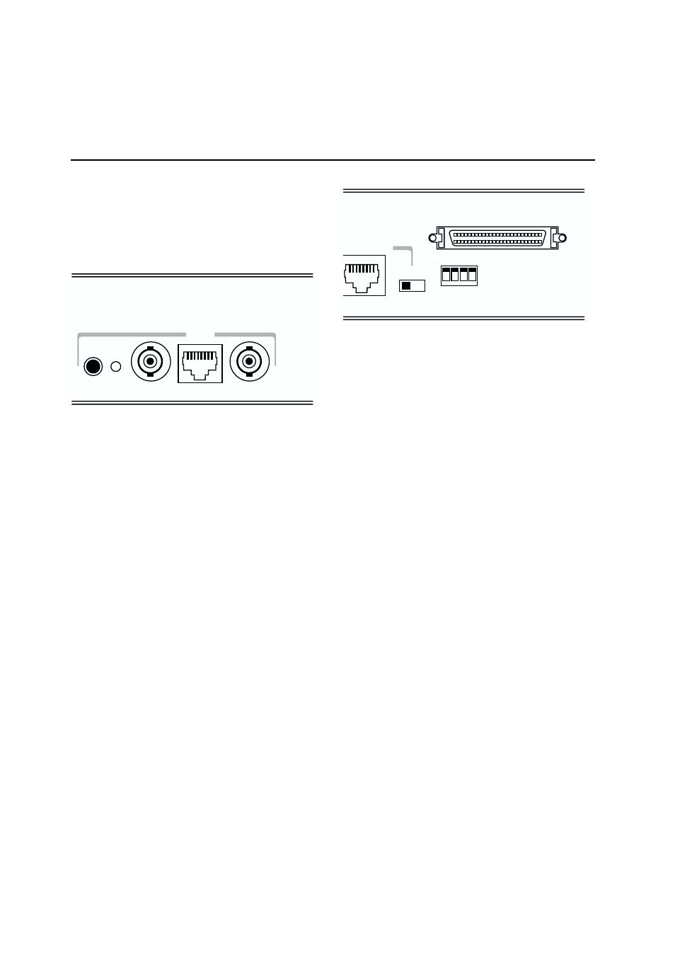
Connect the ISDN service provider’s termination point to the Primary Rate ISDN port
on the rear panel of the AT-AR390 or AT-AR395 router using an approved ISDN
120
Ω cable or 75Ω cable pair.
3 Using the push button to the left of the PRI interface, set
the 120
Ω LED to match the cable type used. If a 120Ω cable is
used, press the push button until the LED is lit. If a 75
Ω cable
pair is used, press the push button until the LED is not lit.
4 Check the operation by observing the state of the LEDs on
the front panel of the router. The Active LED should be lit
indicating the link to the NT is operational. The TxD and RxD
LEDs will be lit as data packets are transmitted and received on
any B channel or the D channel. See Configuring ISDN,
Configuring an IP Network and Configuring a Novell IPX Network
later in this guide for more information about configuring ISDN
calls and routing protocols.
CONNECTING TO A LEASED LINE CIRCUIT
To connect an AT-AR350, AT-AR370(S) or AT-AR370(U) router
with a synchronous interface to a leased line circuit, follow these
steps:
1 Using the appropriate approved transition cable (RS-232,
X.21 or V.35), connect the synchronous port on the rear of the
router to the NTU supplied by the telecommunications
network provider.
Note: If you wish to make your own cable, see the AR Router
Hardware Reference for a detailed description of how to wire a
transition cable.
THERNET 0
SYNCHRONOUS 0
HUB
PC
CONFIG
MDX
4
3
2
1
Connect the NTU to the synchronous port on the rear panel of the AR300 router
using the appropriate transition cable.
2 Check the configuration of the port, by typing the command:
SHOW SYN=0
Verify that the information displayed is correct. In particular,
“State” should be set to “enabled” and “Interface type” should
match the transition cable used.
3 Configure a data link layer module, such as PPP (Point-to-Point
Protocol), Frame Relay or X.25 LAPB, to use the synchronous
interface. To create a PPP interface 0 over synchronous port 0,
type the command:
CREATE PPP=0 OVER=SYN0
4 Check the configuration by typing the commands:
SHOW SYN=0
SHOW PPP=0
The output of the SHOW SYN command should show “Active”
set to “yes” and “Module” set to “ppp”. The output of the
SHOW PPP command should show interface ppp0 over syn0
with “LCP” as the control protocol.
5 Check the operation by observing the state of the LEDs on
the front panel of the router. The Txd and Rxd LEDs will be lit
when data is sent or received on the synchronous interface.
6 For more information about configuring Frame Relay or
X.25 services, see the AR Series Router Software Reference.
CONNECTING A TERMINAL OR MODEM
To connect a terminal or modem to any AR300 Series router,
follow these steps:
1 Use the supplied console cable or an approved terminal
cable to connect a terminal to an asynchronous port on the
rear panel of the router, or use an approved modem cable to
connect a modem to an asynchronous port on the rear panel
2 Connect an approved ISDN 120
Ω cable or 75Ω cable pair
from the ISDN service provider’s termination point to the PRI
interface on the rear panel of the router.
Note: If you wish to make your own ISDN cables, see the AR
Router Hardware Reference for a detailed description of how to
wire an ISDN interface cable.