Chapter 2: installation 24 – Allied Telesis AT-FS202SC/FS1 User Manual
Page 34
Chapter 2: Installation
24
Note
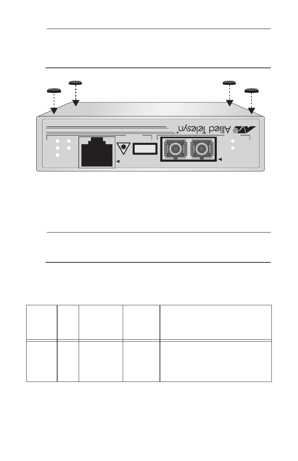
Do not attach the protective feet if you are wallmounting the unit,
installing it in an AT-WLMT-010 wallmount bracket or in an
AT-MCR12 chassis.
Figure 10. Attaching the Protective Feet
4. Configure the DIP switches. Refer to Figure 7 on page 5 for the
location of the DIP switches and Table 5 for the possible settings.
Note
A change to the DIP switch setting does not take effect until after
you reset the unit. To reset the unit, power the unit OFF then ON.
Table 5 lists the descriptions of the DIP Switch settings.
Table 5. DIP Switch Settings
DIP
Switch
No.
Port
Setting
Position
Description
1
2
Speed
(Mbps)
Up
Down
The twisted pair port operates
at 10 Mbps.
The twisted pair port operates
at 100 Mbps.
940
10Base-T/100Base-TX
AT-FS202
BRIDGING MEDIA CONVER
TER IEEE 802.3/802.3U
AUTO MDI/MDI-X
LNK/
ACT
FD/
COL
PWR
AUTO
NEG
100M
LNK/
ACT
FD/COL
PORT 2
100Base-FX
TX
RX
PORT 1
MULTI MODE
CLASS 1
LASER PRODUCT