Installing the switch in a rack, Figure 8. attaching the mounting brackets, Chapter 2: installation 38 – Allied Telesis AT-GS900/8POE User Manual
Page 38: Class 1 lase r pro duct, Pd on pd er r link act clas s 1 laser pro duct
Chapter 2: Installation
38
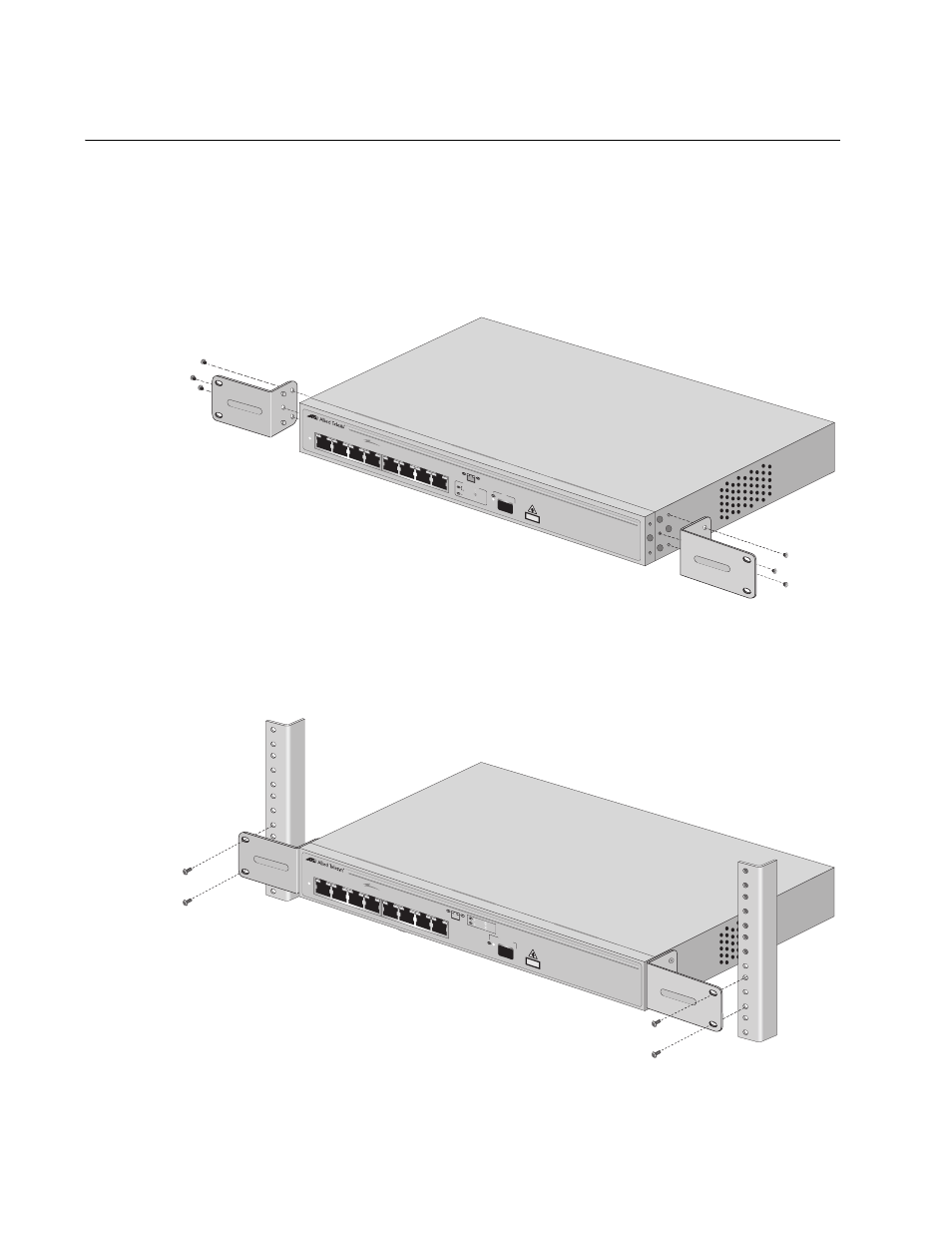
Installing the Switch in a Rack
To install the switch in a rack, perform the following procedure:
1. If attached, remove the rubber feet using a flat-head screwdriver.
2. Attach a mounting bracket (provided) to each side of the switch using
the bracket mounting screws (provided), as shown Figure 8.
Figure 8. Attaching the Mounting Brackets
3. Mount the switch on a 19-inch rack using the screws (not provided), as
shown in Figure 9.
965
POWE
R
1
2
3
4
5
6
7
8R
PoE
CLASS
1
LASE
R PRO
DUCT
1000B
ase-X
AT-G
S900/
8POE
8 Port 10
/100/1
000 M
bps PO
E Sw
itch with 1
Com
bo SFP P
ort
PD O
N
PD E
RROR
1000
LINK
ACT
10/100
LIN
K
ACT
PO
RT AC
TIVITY
8
SFP
776
AT-FS
708/P
OE
8 po
rt 10/100
TX Unma
nage
d POE
Switc
h w
/1 SFP
port
POWER
1
2
3
4
5
6
7
8
PoE
SFP
UPLIN
K POR
T
PD ON
PD ER
R
LINK
ACT
CLAS
S 1
LASER PRO
DUCT
1000Ba
se-X
- AT-GS908M (54 pages)
- AT-x230-10GP (80 pages)
- AT-GS950/10PS (386 pages)
- AT-GS950/48PS (64 pages)
- AT-GS950/16PS (386 pages)
- AT-GS950/48PS (386 pages)
- AT-9000 Series (1480 pages)
- AT-9000 Series (258 pages)
- IE200 Series (70 pages)
- AT-GS950/48 (410 pages)
- AT-GS950/8 (52 pages)
- AT-GS950/48 (378 pages)
- AT-GS950/48 (60 pages)
- SwitchBlade x8106 (322 pages)
- SwitchBlade x8112 (322 pages)
- SwitchBlade x8106 (240 pages)
- SwitchBlade x8112 (240 pages)
- AT-TQ Series (172 pages)
- AlliedWare Plus Operating System Version 5.4.4C (x310-26FT,x310-26FP,x310-50FT,x310-50FP) (2220 pages)
- FS970M Series (106 pages)
- 8100L Series (116 pages)
- 8100S Series (140 pages)
- x310 Series (120 pages)
- x310 Series (116 pages)
- AT-GS950/24 (404 pages)
- AT-GS950/24 (366 pages)
- AT-GS950/16 (44 pages)
- AT-GS950/16 (364 pages)
- AT-GS950/16 (404 pages)
- AT-GS950/8 (404 pages)
- AT-GS950/8 (364 pages)
- AT-GS950/8 (52 pages)
- AT-8100 Series (330 pages)
- AT-8100 Series (1962 pages)
- AT-FS970M Series (330 pages)
- AT-FS970M Series (1938 pages)
- SwitchBlade x3106 (288 pages)
- SwitchBlade x3112 (294 pages)
- SwitchBlade x3106 (260 pages)
- SwitchBlade x3112 (222 pages)
- AT-S95 CLI (AT-8000GS Series) (397 pages)
- AT-S94 CLI (AT-8000S Series) (402 pages)
- AT-IMC1000T/SFP (23 pages)
- AT-IMC1000TP/SFP (24 pages)
- AT-SBx3106WMB (44 pages)