Connectors and port pinouts, Rj-45 connector and port pin layout, Mdi pin signals (10base-t or 100base-tx) – Allied Telesis AT-GS950/48 User Manual
Page 50: Mdi-x pin signals (10base-t or 100base-tx)
Appendix A: Technical Specifications
50
Connectors and Port Pinouts
This section lists the connectors and connector pinouts.
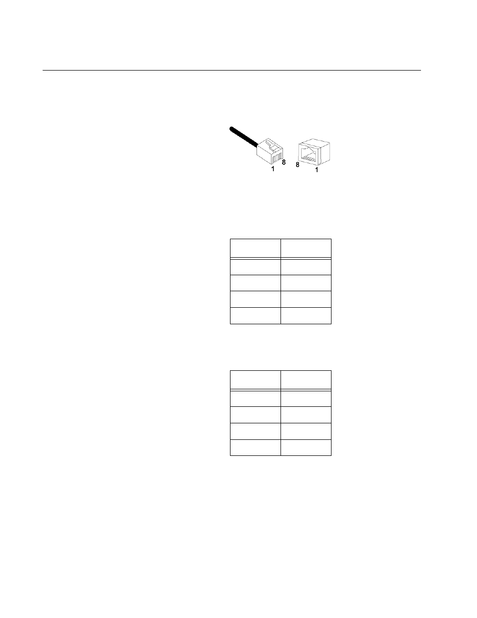
Figure 16 illustrates the pin layout for an RJ-45 connector and port.
Figure 16. RJ-45 Connector and Port Pin Layout
Table 11 lists the RJ-45 pin signals when a twisted pair port is operating in
the MDI configuration.
Table 12 lists the RJ-45 port pin signals when a twisted pair port is
operating in the MDI-X configuration.
Table 11. MDI Pin Signals (10Base-T or 100Base-TX)
Pin
Signal
1
TX+
2
TX-
3
RX+
6
RX-
Table 12. MDI-X Pin Signals (10Base-T or 100Base-TX)
Pin
Signal
1
RX+
2
RX-
3
TX+
6
TX-
This manual is related to the following products: