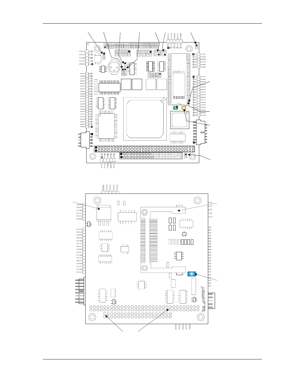
Figure 2-5. jumper and led locations (top view), Figure 2-6. connector location (bottom view) – Ampro Corporation CoreModule 420 5001692A User Manual
Page 19
Chapter 2
Product Overview
CoreModule 420
Reference Manual
13
U5
J3
JP2
J4
U6
U15
U16
D1
D2
U14
U8
U7
U9
U10
J8
JP7
JP8
JP
9
JP6
U36
U35
U3
U4
0
U41
U11
L5
J2
P1
J7
J10
J11
J9
U1
2
D8
U13
J13
J14
J5
JP4
JP5
9
10
10
2
4
3
1
1
2
1
2
JP1
JP2
Link/Activity
LED (D1)
Speed
LED (D2)
JP6
JP9
Bytewide
Socket (U5)
Pin-1
JP4
JP5
JP8
JP7
JP1
C
M
4
20R
F
M
_01c
Figure 2-5. Jumper and LED Locations (Top View)
D5
U21
U4
2
Y2
Y3
Y1
U2
9
U2
5
U3
8
U2
7
U3
0
U2
8
F1
J12
U23
U24
U19
U1
D3
D4
U3
7
U20
U2
2
CompactFlash
Socket (J12)
PC/104 Bus (P1)
USB Fuse (F1)
Voltage
Regulator
(U19)
C
M
420R
F
M
_02
a
Figure 2-6. Connector Location (Bottom View)