Jumper definitions, Led definitions, Jumper definitions led definitions – Ampro Corporation CoreModule 420 5001692A User Manual
Page 18
Chapter 2
Product Overview
12
Reference Manual
CoreModule 420
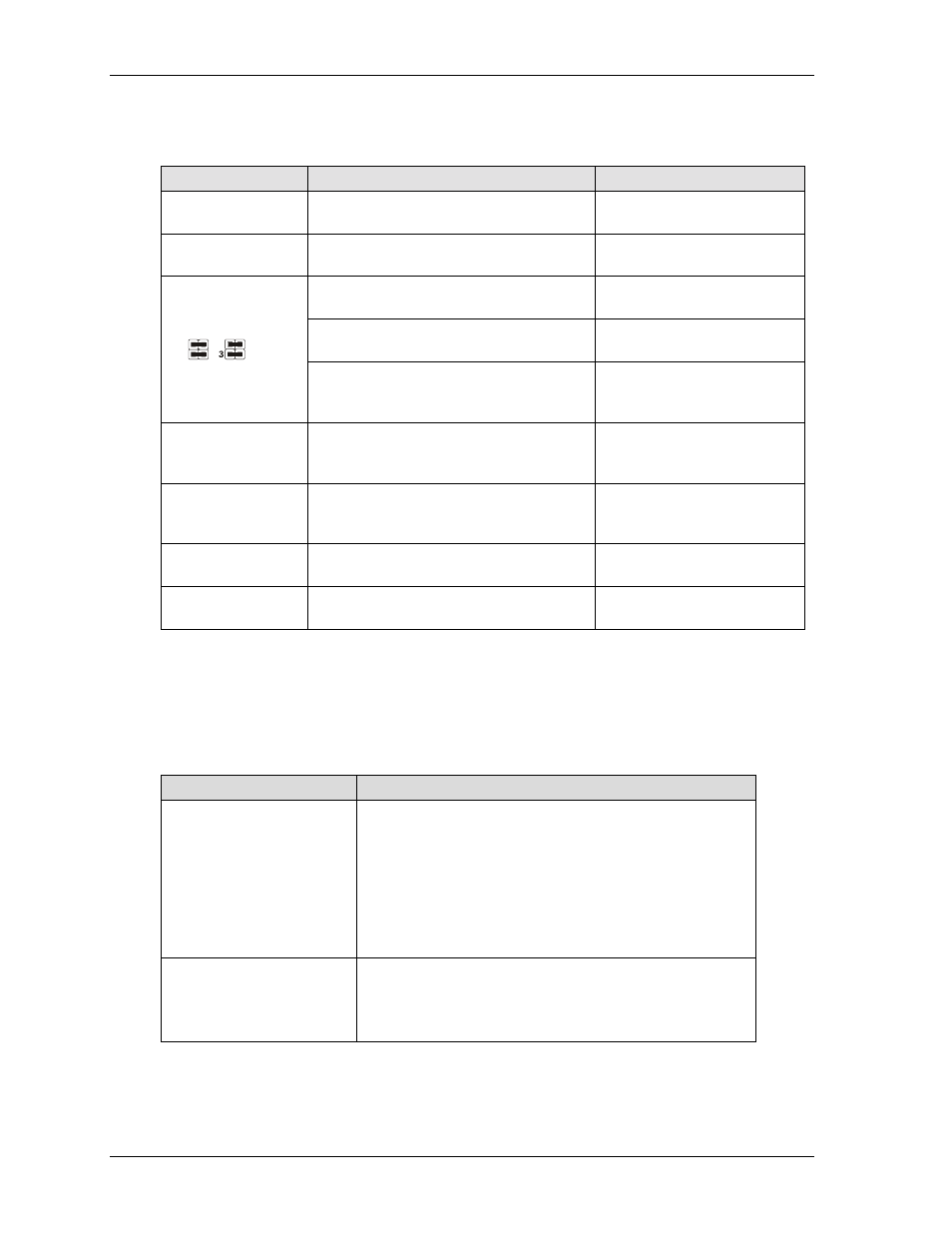
Jumper Definitions
Table 2-3 describes the jumpers shown in Figure 2-5.
Table 2-3. Jumper Settings
Jumper #
Installed
Removed
JP1 Serial Port 1
Termination
Enable RS485 Termination
(Pins 1-2)
Disable RS485 Termination
(No jumper) Default setting
JP2 Serial Port 2
Termination
Enable RS485 Termination
(Pins 1-2)
Disable RS485 Termination
(No jumper) Default setting
Enable Internal BIOS – Normal operation,
(Pins 1-3 on both JP4 & JP5)
Disabled – Won’t Boot
(See other positions)
Enable External BIOS – Used for recovery
(Pins 1-2 on both JP4 & JP5)
Disabled – Won’t Boot
(See other positions)
JP4 & JP5
BIOS/DOC Select
BIOS/DOC Select
Jumper Setting
(Shown in Default)
1
4
2
1
2
3
4
JP4
JP5
Enable DOC – Boot from DiskOnChip in
bytewide socket (Pins 1-3 & 2-4 on both
JP4 & JP5) Default setting
Disabled – Won’t Boot
(See other positions)
JP6
Flat Panel Voltage
Selection
+3.3 Volts (Pins 1-2)
+5 Volts (Pins 2-3)
JP7
DiskOnChip Boot
Address Select
Access from DC000h-DDFFFh
(Pins 1-2)
Access from CC000h-CDFFFh
(No jumper)
JP8 Serial Port 1
Enable Serial Port 1
(Pins 1-2) Default setting
Disabled Serial Port 1
(Pins 2-3)
JP9 Serial Port 2
Enable Serial Port 2
(Pins 1-2) Default setting
Disabled Serial Port 2
(Pins 2-3)
Note: JP8 and JP9 Enable/Disable the Serial ports at the STPC Altas CPU (U14).
LED Definitions
Table 2-4 provides the LED color and definitions for the Ethernet Port (J2) located on the CoreModule
420 and Figure 2-5 provides the locations.
Table 2-4. Ethernet Port (J2) LED Indicators
Indicator
Definition
Ethernet
Link/Activity LED (D1)
Link/Activity LED – This yellow LED is the activity/link
indicator and provides the status of Ethernet port (J2).
The Link/Activity LED indicates an Link is established with
either transmit or receive activity.
Yellow On – This indicates a link is present.
Yellow Flashing – This indicates activity is present.
Yellow Off – This indicates no link or activity is present.
Ethernet Speed (D2)
Speed LED – This green LED is the LAN Speed indictor and
indicates the
transmit or receive speed of
Ethernet port (J2).
Green On – This indicates the operating speed is 100Mbps
Green Off – This indicates the operating speed is 10Mbps.