2 wiring, 1 serial wiring (comn), 2 serial wiring (sdm-sio1) – Campbell Scientific WINDSONIC 2-D Sonic Wind Sensors User Manual
Page 19: Wiring, Serial wiring (comn), Serial wiring (sdm-sio1), 2. windsonic1 to datalogger connections, 3. windsonic1 to sdm-sio1 connections
WindSonic Two-Dimensional Sonic Anemometer
7.2 Wiring
7.2.1 Serial Wiring (COMn)
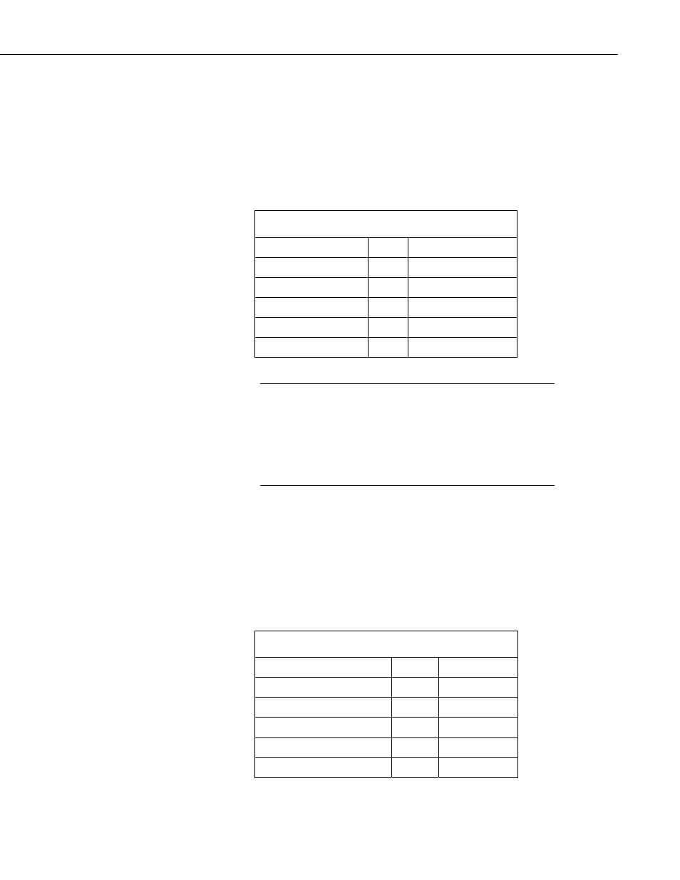
CRBasic dataloggers (CR800 series, CR1000, and CR3000) support serial
communications with dedicated UART hardware on the datalogger control
ports. Two control ports can be configured as a single communications
(COMn) port. The WindSonic1 serial interface uses four wires as shown in
TABLE 7-2.
TABLE 7-2. WindSonic1 to Datalogger Connections
Description Color
CRBasic
Datalogger
WindSonic RxD
Green COMn Tx
WindSonic TxD
White COMn Rx
Power Red
12
Vdc
Serial/power reference Black G
Shield Clear
G
The maximum cable length that can be used with a RS-232
interface depends on the baud rate, the nominal resistance of the
wire, the capacitance between conductors, and the capacitance
between the conductors and the shield. According to the
Electronic Industries Association RS-232D standard, a rough
rule of thumb is to limit RS-232 cable lengths to 15.24 m (50
feet) or less at 9600 baud.
NOTE
7.2.2 Serial Wiring (SDM-SIO1)
CRBasic dataloggers support serial communications using the SDM-SIO1
peripheral. The SDM-SIO1 converts RS-232 signals into Synchronous Device
for Measurements (SDM). SDM is a Campbell Scientific digital
communications protocol used between Campbell Scientific dataloggers and
SDM peripherals. At a 1 Hz measurement rate, a maximum of 4 WindSonic1s
can be measured by a datalogger. TABLE 7-3 describes the connections
between a WindSonic1 and SDM-SIO1.
TABLE 7-3. WindSonic1 to SDM-SIO1 Connections
Description Color
SDM-SIO1
WindSonic RxD
Green
TX-Z
WindSonic TxD
White
RX-A
Power Red
+12V
Serial/power reference
Black
G
Shield Clear
G
11