Programming, 1 programming overview – Campbell Scientific CS547A-L Conductivity/Temperature Probe and A547A Interface User Manual
Page 10
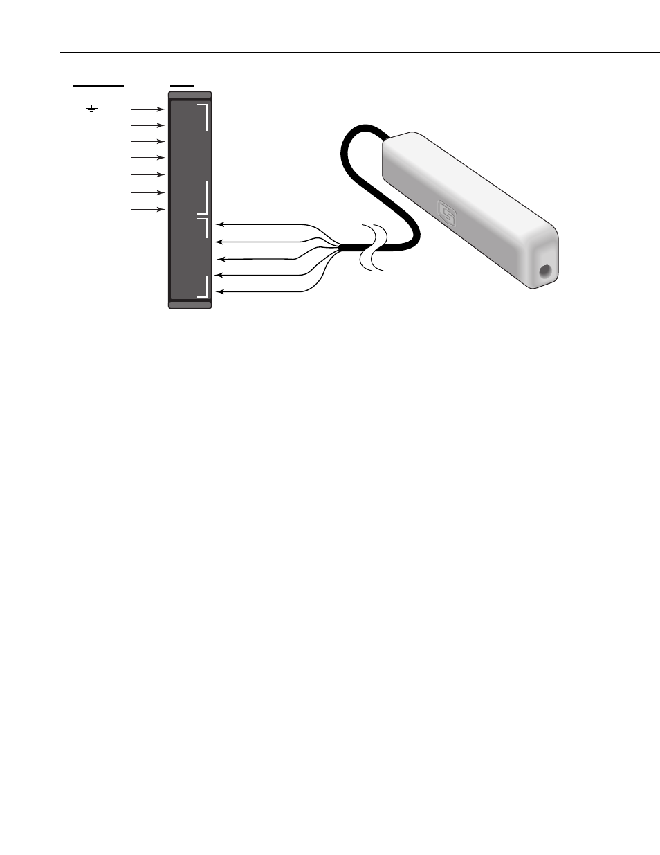
CS547A Conductivity and Temperature Probe and A547 Interface
Datalogger
AG
SE TEMP
EX TEMP
D
A
T
ALOGGER
SENSOR
EX TEMP
TEMP
COND
EX COND
EX COND
HI COND
LO COND
SHIELD
SHIELD
FIGURE 4-1. CS547A wiring diagram for example below
5. Programming
All example programs may require modification by the user to fit the specific
application's wiring and programming needs. All program examples in this
manual are for the CR10(X) or CR1000 and assume that datalogger is wired to
the A547 interface are as follows: the LO COND lead is connected to 1L, the
HI COND to 1H, the EX COND to VX1 or EX1, the EX TEMP to VX2 or
EX2, and the SE TEMP to SE3.
Public Variable Declarations / Input Location Labels
Definitions for the following program:
Rs
Solution resistance
Rp
Resistance of leads/cable and blocking caps
Ct
Solution EC with no temp. correction
Temp_degC
Solution temperature in °C
C25mScm_1 EC corrected for temperature
5.1 Programming Overview
Typical datalogger programs to measure the CS547A consist of four parts:
1. Measurement of EC and temperature
EC: Resistance across the electrodes is computed from the results of the
BrFull (P6) or BrHalf (P5) instructions (chosen automatically as part of
the autoranging feature) followed by the Bridge Transformation algorithm
(P59).
or AG
SE3
VX2 or EX2
VX1 or EX1
1H
1L
Ground
Clear (Shield)
Red (Temp)
Orange (Cond)
Black (Ex Cond)
Green (Ex Temp)
A547
4