B.2.5 cr10x-pb table-based datalogger example, B.2.5 cr10x-pb, Table-based – Campbell Scientific CS475, CS476, and CS477 Radar Water Level Sensor User Manual
Page 48: Datalogger example....................... b-10
Appendix B. SDI-12 Commands/Changing Settings
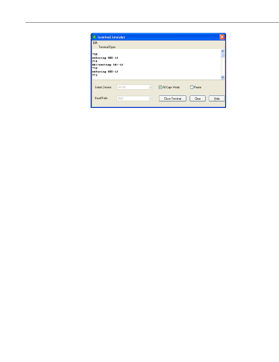
FIGURE B-4. SDI-12 transparent mode on CR10X datalogger using
control port 1 and changing SDI-12 address from 0 to 1
B.2.5 CR10X-PB Table-Based Datalogger Example
1. Connect a single sensor to the datalogger as follows:
• White to Control Port C1
• Black, Orange, Clear to G
• Red to 12V
2. Download a datalogger program that contains the SDI-12 Recorder (P105)
instruction with valid entries for each parameter. Make sure that
parameter 3 of the P105 instruction matches the control port number where
the green wire is connected.
3. In the LoggerNet Connect screen navigate to the Datalogger menu and
select Terminal Emulator. The “Terminal Emulator” window will open.
In the Select Device menu, located in the lower left-hand side of the
window, select the CR10XTD or CR10XPB station.
4. Click on the Open Terminal button.
5. Press the
6. To activate the SDI-12 Transparent Mode on Control Port p, enter *8. The
TD datalogger will respond with a “.” prompt. At the “.” prompt enter #.
The TD datalogger will respond with 150000. Finally, enter p (Control
Port p) and press the
datalogger will respond with “entering SDI-12”. If any invalid
SDI-12 command is issued, the datalogger will exit the SDI-12
Transparent Mode.
7. To query the sensor for its current SDI-12 address, enter the command ?!.
The sensor will respond with the current SDI-12 address.
B-10