Table 4-2 and table 4-3 – Campbell Scientific CS475, CS476, and CS477 Radar Water Level Sensor User Manual
Page 11
CS475, CS476, and CS477 Radar Water Level Sensor
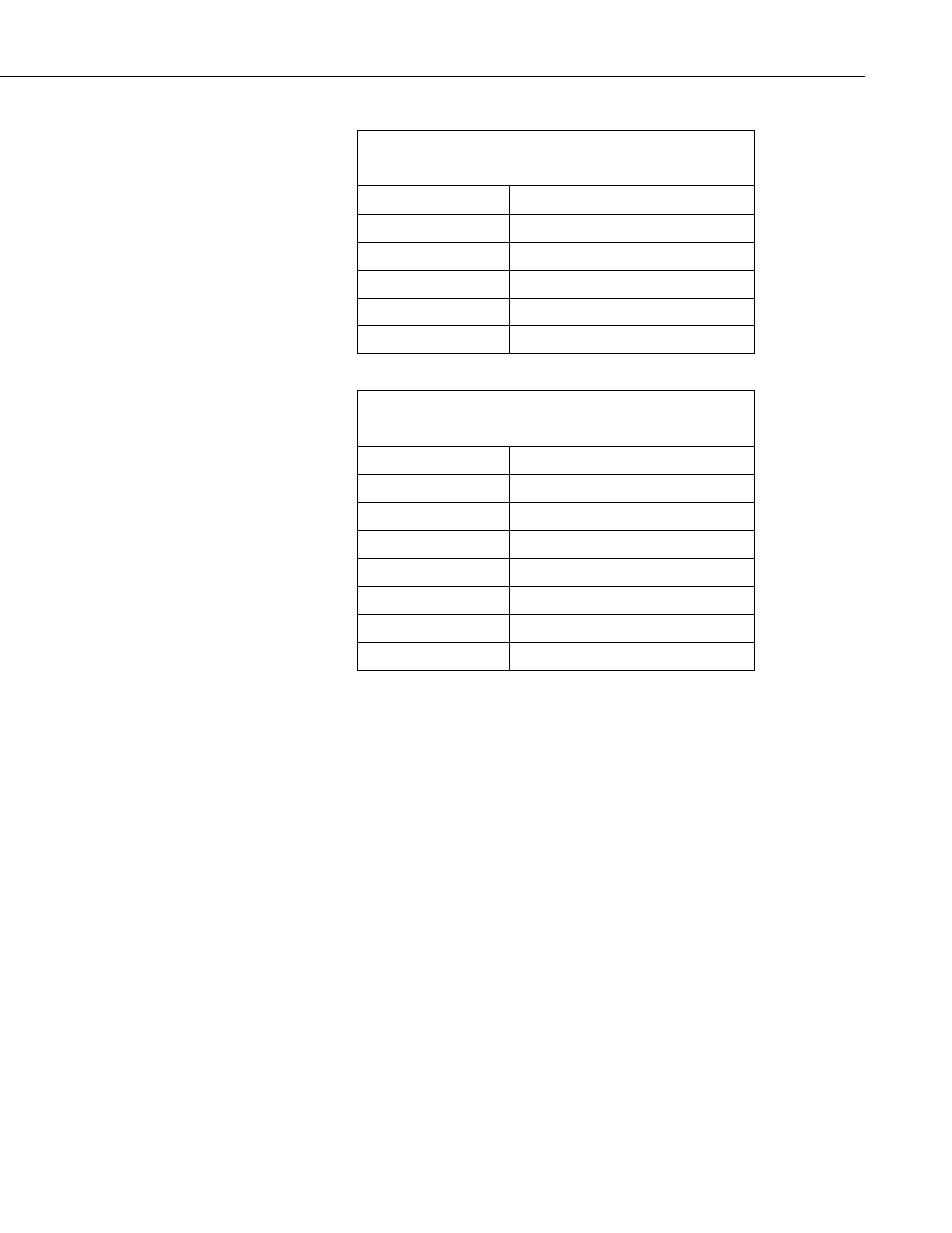
TABLE 4-2. Radiation Beam Spread for CS475
(10° Beam Angle)
Distance in Meters
Diameter of Footprint in Meters
1 0.18
5 0.87
10 1.76
15 2.64
20 3.53
TABLE 4-3. Radiation Beam Spread for CS476/CS477
(8° Beam Angle)
Distance in Meters
Diameter of Footprint in Meters
1 0.14
5 0.70
10 1.41
15 2.11
20 2.81
30 4.216
70 (CS477 only)
9.84
3. Securely mount the sensor.
4. Use a user-supplied bubble level or the 25619 bubble level to make certain
the antenna horn is aligned within 1° of vertical. The cap needs to be
removed when using the 25619. If the antenna is not vertical, a
trigonometric measurement error can occur with respect to the water. The
maximum range is reduced because of the off-axis return signal.
5. Orient the sensor such that one of its polarization markings is aligned
towards the wall or pier (see FIGURE 4-1 and TABLE 4-4).
3