B.2.3 cr1000 datalogger example, B.2.3 cr1000 – Campbell Scientific CS475, CS476, and CS477 Radar Water Level Sensor User Manual
Page 46
Appendix B. SDI-12 Commands/Changing Settings
B.2.3 CR1000 Datalogger Example
1. Connect a single sensor to the datalogger as follows:
• White to Control Port C1
• Black, Orange, Clear to G
• Red to 12V
2. In the LoggerNet Connect screen navigate to the Datalogger menu and
select Terminal Emulator. The “Terminal Emulator” window will open.
In the Select Device menu, located in the lower left-hand side of the
window, select the CR1000 station.
3. Click on the Open Terminal button.
4. Press the
prompt. At the “CR1000>” prompt, make sure the All Caps Mode box is
checked and enter the command SDI12
3, 5, or 7” prompt, key in the control port number where the sensor’s white
lead is connected and
indicates that the sensor is ready to accept SDI-12 commands.
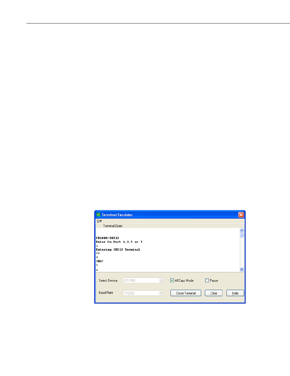
5. To query the sensor for its current SDI-12 address, key in ?!
the sensor will respond with its SDI-12 address. If no characters are typed
within 60 seconds, then the mode is exited. In that case, simply enter the
command SDI12 again, press
number when prompted.
FIGURE B-3. SDI-12 transparent mode on CR1000 datalogger using
control port 1 and changing SD1-12 address from 3 to 1
6. To change the SDI-12 address, key in aAb!
current address from the above step and b is the new address. The sensor
B-8