5 power/data connector – Matrix Orbital GLK24064-25 Legacy User Manual
Page 15
2.5
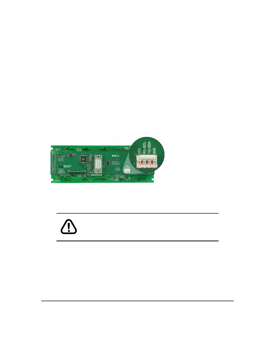
Power/Data Connector
The Power/Data Connector provides a standard connector for powering the display module. The GLK24064-
25 requires five volts for the standard display module, between nine to fifteen for the wide voltage (V) and
between nine to thirty-five volts for the wide voltage with efficient power supply module (VPT). The volt-
age is applied through pins one and four of the four pin Power/Data connector. Pins two and three are
reserved for serial transmission, using either the RS-232/TTL or the I
2
C protocol, depending on what has
been selected by the Protocol Select Jumpers. Pins two and three may be reversed by changing the Legacy
Connector Jumpers in order to be compatible with previous PCB revisions.
Pin
1
PWR
(See table ?? on page ??)
Pin
2
Rx \ SCL (I
2
C clock)
Pin
3
Tx \ SDA (I
2
C data)
Pin
4
GND
Figure 17: Power Connector and Pin-out
WARNINGS
• Do not apply any power with reversed polarization.
• Do not apply any voltage other than the specified voltage.
2.5.1
Legacy Data Connector Jumpers
To reverse pins two and three of the Power/Data Connector remove the zero ohm resistors from the
Legacy Data Connector Jumpers, labeled with the
=
symbol and place them on the jumpers labeled with the
X
symbol. This will allow you to transmit on pin two, and receive data on pin three instead of the default
of receiving on pin two and transmitting on pin three of the Power/Data Connector.
Matrix Orbital
GLK24064-25
10