1 db-9 connector, 1 power through db-9 jumper – Matrix Orbital GLK24064-25 Legacy User Manual
Page 11
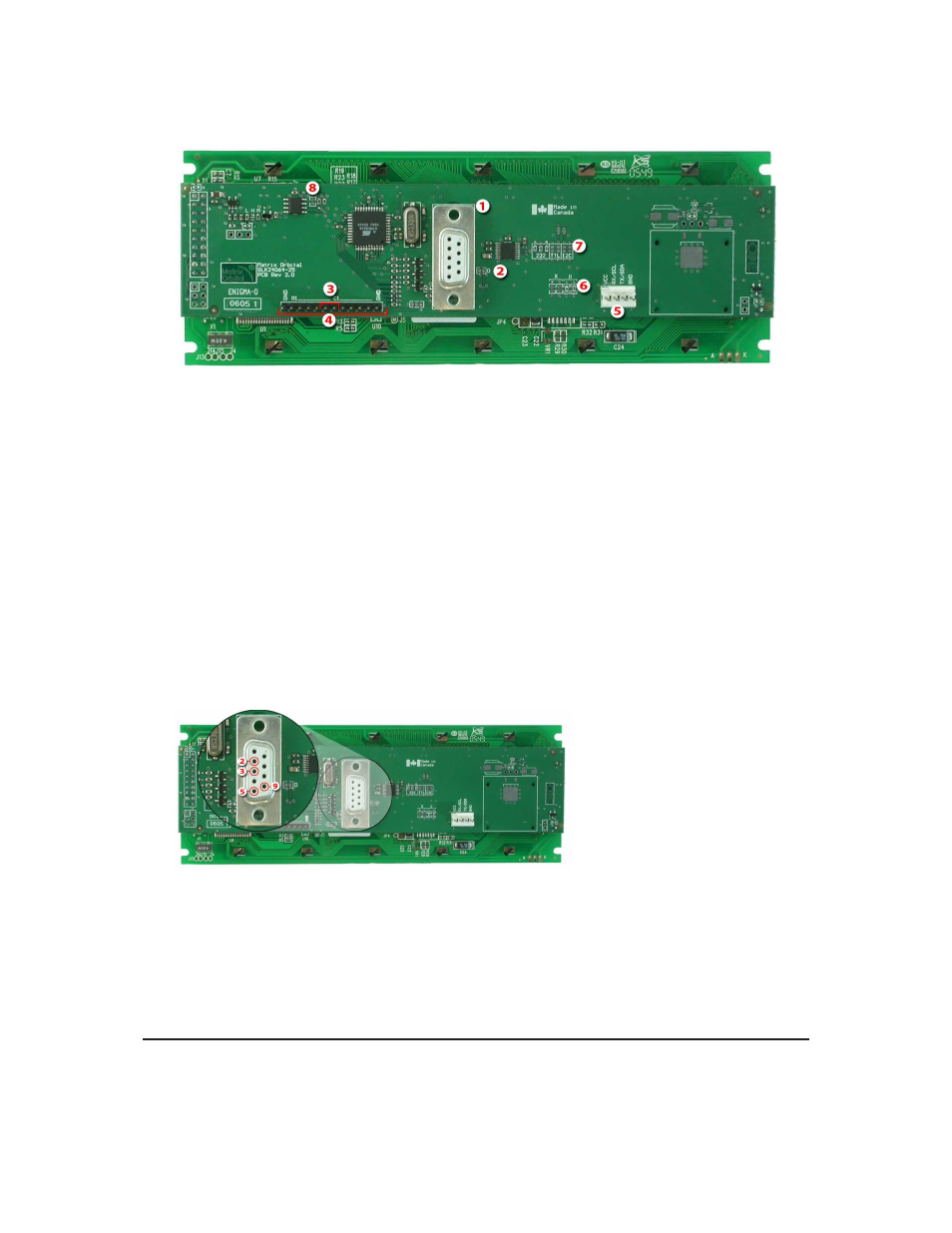
1
DB-9 Connector
5
Power / Data Connector
2
Power Through DB9 Jumper
6
Legacy Connector Jumper
3
Manual Override
7
Protocol Select Jumpers
4
Keypad Interface Connector
8
Filesystem Lock Jumper
Figure 11: GLK24064-25
2.1
DB-9 Connector
The GLK24064-25 provides a DB-9 Connector to readily interface with serial devices which use the
EIA232 standard signal levels of ±12V to ±12V. It is also possible to communicate at TTL levels of 0 to
+5V by setting the Protocol Select Jumpers to TTL. As an added feature it is also possible to apply power
through pin 9 of the DB-9 Connector in order to reduce cable clutter. However, in order to accomplish this
you must set the Power Through DB-9 Jumper.
Pin
2
Tx \ SDA (I
2
C data)
Pin
3
Rx \ SCL (I
2
C clock)
Pin
5
GND
Pin
9
PWR
(Must solder Power Through DB-
9 Jumper. See table ?? on page ?? for
power requirements.)
Figure 12: RS-232 Pin-out
2.1.1
Power Through DB-9 Jumper
In order to provide power through pin 9 of the DB-9 Connector you must place a solder jumper on the
Power through DB-9 Jumper pictured in
figure 13
below. The GLK24064-25 allows all voltage models to
Matrix Orbital
GLK24064-25
6