Output state – Ashcroft GC55 - Differential Pressure Transducer with Digital Display User Manual
Page 9
9
5. noise Prevention
Power supply
If noise is present in the power supply / wires the pressure display can fluc-
tuate and provide incorrect output. Care should be taken to keep the GC55
power supply wires from high voltage lines and use a power line with a high
noise rejection ratio.
6. storage
Store in a location in compliance with the environmnetal rating of the unit
and within –20 to +60C (–4 to 140F).Avoid direct exposure of the display to
sunlight
7. Maintenance
Although this is a solid state device a twice yearly visual inspection is rec-
ommended along with regular zero adjustment if necessary.
8. Menu navigation
Functions
PLEASE NOTE: Only the “SEL” function is available from the case exterior,
accesss to all other functions requires the cover to be removed. Do not use
sharp objects to press the keys as this can puncture the panel. See illustra-
tion 1 and illustration 2.
External Panel and Functions (SEL key can be operated externally)
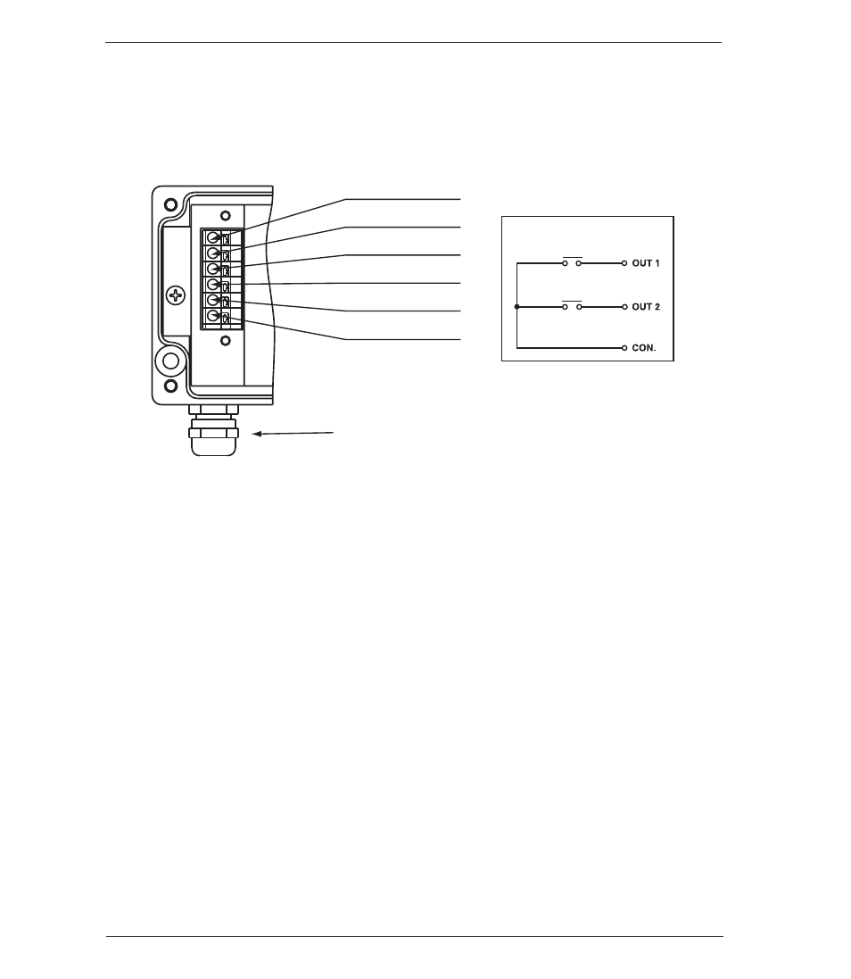
4. Wiring
Terminal strip Designations
The terminals are as shown below. Connect power only after checking wiring.
After power is turned on, wait at least 15 minutes before performing a zero
adjustment or measurement.
Power supply (
−)
Power supply (
+)
Cable Gland or 1/2 FNPT
Conduit Connection
COM. (Switch)
OUT 2 (Switch)
OUT 1 (Switch)
Analog output
Applicable wire
16-22 AWG
output state