Aalborg PWE Digital User Manual
Page 10
5
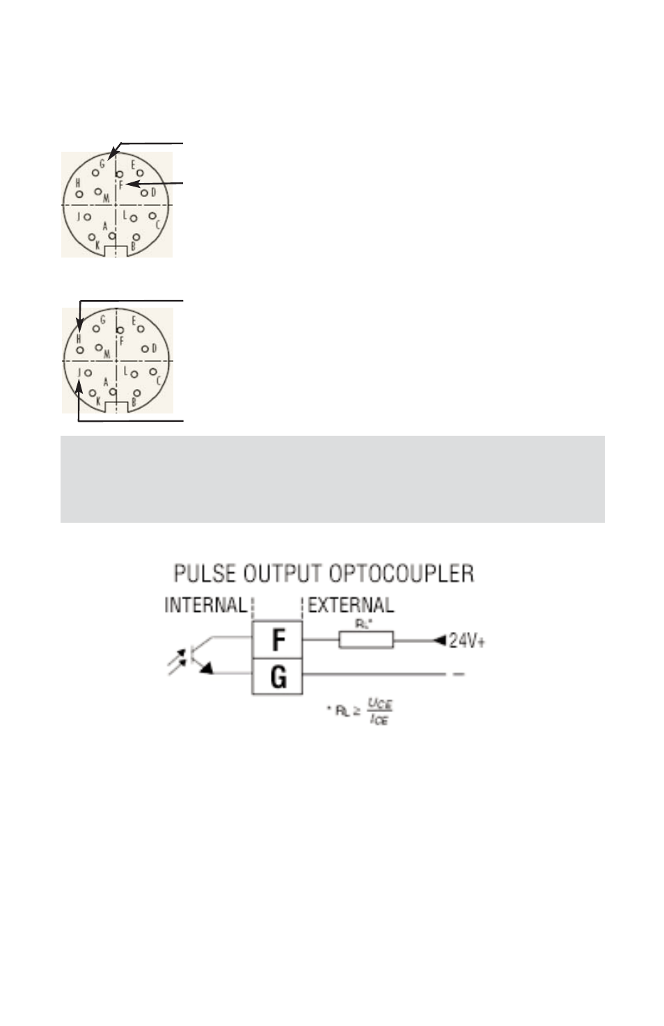
2.2.4 Programmable optically isolated Output
Signals Connections
Optocoupler #1 (pins F and G):
Pin F ------------ Plus (+) (passive)
Pin G ------------ Plus (-) (passive)
Optocoupler #2 (pins H and J):
Pin H ------------ Plus (+) (passive)
Pin J ------------ Plus (-) (passive)
2.2.5 Communication Parameters and Connections
The digital interface operates via RS485 (optional RS-232) and provides access to
applicable internal data including: flow, temperature, totalizers and alarm settings,
flow linearizer table, fluid density and engineering units selection.
WARNING: Optically isolated outputs require application of DC voltage
across terminals. Do not exceed maximum allowed limits for voltage
and current provided below:
ƽ