Installation example, Cables – Videotec DCRE485 User Manual
Page 18
Page 4 DCRE485 0600
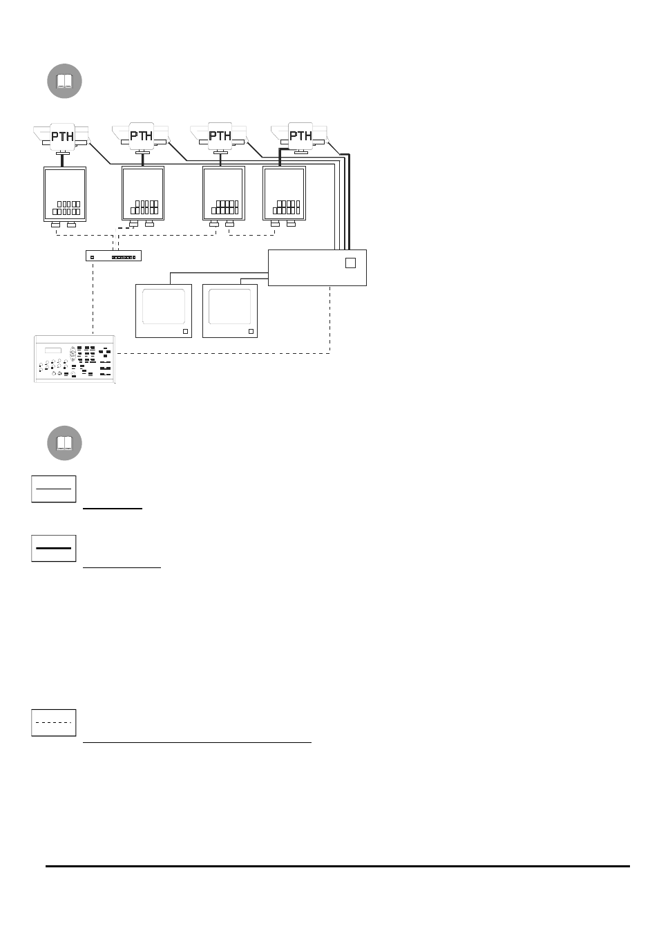
Installation example
One operator with more than one monitor, controlling a series of pan & tilt motors in a mixed configuration (star
and cascade)
MATERIAL
Control part:
1 keyboard DCS3
Video part:
1 video switcher SW328
2 monitors
4 cameras
Telemetry part:
1 data distributor DCRE485
4 receivers DTMRX1
4 pan & tilt motors
Cables
In the above scheme, different lines have been used to show different types of functions:
video cable:
coaxial RG 59 or equivalent cable.
multipolar cable:
each pan & tilt function is enabled / desabled by a relay inside the receiver.
Define the cable final number, following these indications:
7 wires for pan & tilt movement: right, left, high, low, autopan, common, ground
6 control wires for reverse polarity zoom lenses (zoom, focus, iris)
4 control wires for common ground zoom lenses (zoom, focus, iris)
2 wires for the auxiliary
Note: it is advisable to use different multipolar cables for low tension and high tension functions.
Minimum section advised:
0,56 mm.² (AWG 20) for high tension wires (pan & tilt)
0,34 mm.² (AWG 22) for low tension wires (zoom lens, auxiliary)
cable for control digital reception/transmission:
2 wires for the control unit reception (twisted pair cable, section 0,22 mm.² AWG 24)
2 wires for possible transmission to the following receiver in cascade configurations (twisted pair cable, section 0,22
mm.² AWG 24)
Note: the maximum connection distance is about 15 m in RS232; 1500 m in Current Loop.
SW328
DCRE485
DCS3
DTMRX1
DTMRX1
DTMRX1
DTMRX1