5 how to install the blower, 1 housing power supply voltage 100-240vac, 2 12vdc or 24vac power supply – Videotec HEG User Manual
Page 9: 3 closing the housing
EN - English - I
nstruc
tions manual
7
6.1.5.1 Housing power supply voltage 100-
240Vac
Position the power supply supplied with the kit
in the seating provided on the rear cover plate of
the housing. Fix the power supply to the housing
cover plate using the special support and the
screws supplied with the power supply kit (Fig. 08,
page 7).
Insert the 6 pin connector of the power supply cable
in the corresponding connector on the support
circuit, shown as J5 (Fig. 06, page 6).
6.1.5.2 12Vdc or 24Vac power supply
Insert the pre-wired connector supplied with the kit
in the J5 connector on the support circuit to make
operation compatible with the supplied voltage.
Fig. 10
6.1.5.3 Closing the housing
Close the housing by proceeding in the reverse order
to that described above.
h
At the terminal board indicated as J4 on
the support circuit (Fig. 06, page 6)
it is possible to take off the main power
supply voltage originating from an external
source. If the circuit is powered by an
external source take great care to check
the type of voltage used and utilise the
correct power supply kit, according to
requirements.
j
The fan should be assembled on the
cover plate of the housing with the arrow
showing the direction of the air flow
produced by the fan pointing towards
the outside of the housing so as to ensure
correct circulation of the air inside the
housing.
Fig. 11
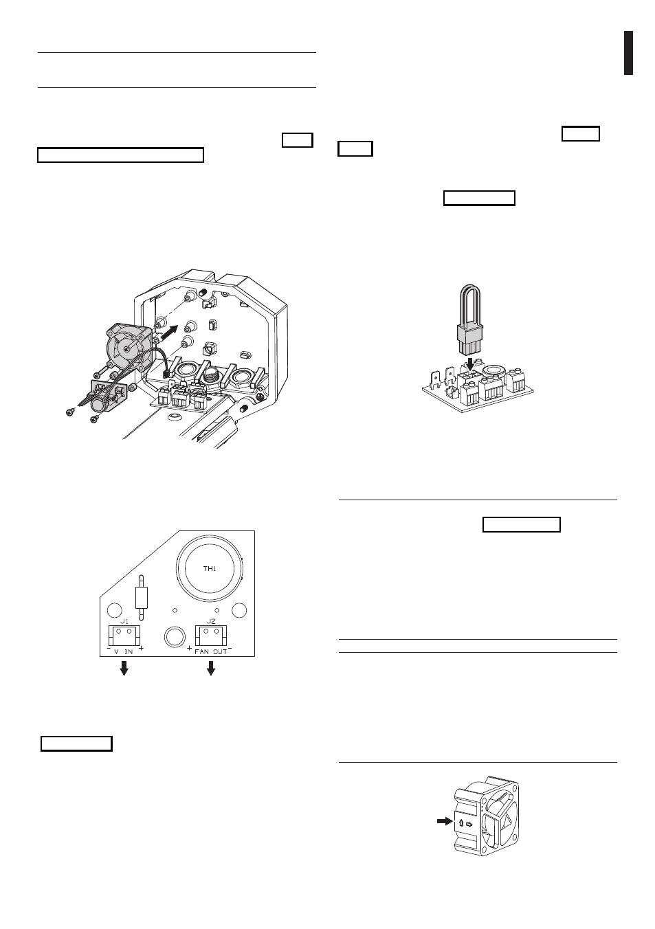
6.1.5 How to install the blower
h
Not applicable to housings with installed
cooling device.
This section describes how to install the fan kit inside
the housing.
Open the housing as in the instructions above ("6.1.1
How to open the housing", page 5).
Position the fan in the seating provided on the rear
cover plate of the housing.
Fix the fan using the two screws supplied with the kit.
Assemble the fan circuit in the seating provided on
the rear cover plate of the housing using the special
screws and spacers supplied with the kit.
Fig. 08
Insert the two-pin connector of the fan cable in the
corresponding FAN OUT (J2) terminal on the fan
circuit.
J2
J1
Fig. 09
Connect the FAN (J6) terminal of the support circuit
(Fig. 06, page 6) on the housing slide to the V IN
(J1) terminal on the fan circuit using the special cable
supplied with the kit.