Teledex Y Series User Manual
Page 9
Y SERIES EXP212, EXP224, AND EXP248 USER GUIDE
www.teledex.com
9
1.2.1 INSTALLATION OVERVIEW
The installation consists of the following
procedures. Each procedure will be explained in
detail in the following sections:
Step 1:
Mount the system into the desired
location of a rack.
Step 2
(EXP212,
EXP224): Connect to the DC power supply,
and then check the voltage. Make
sure the AC power is not connected
before wiring the power cable and
grounding.
Step 2
(EXP248): Turn the power switch in OFF
position. Connect to the DC power
supply, and then check the voltage.
Make sure the power switch is
in OFF position before wiring the
power cable and grounding.
Step 3
(EXP248
only):
Connect FAN cable.
Step 4:
Connect the cable between system
and MDF.
After executing the previous procedures, please
check the cable connection robustness and
correctness before turning on the power supply.
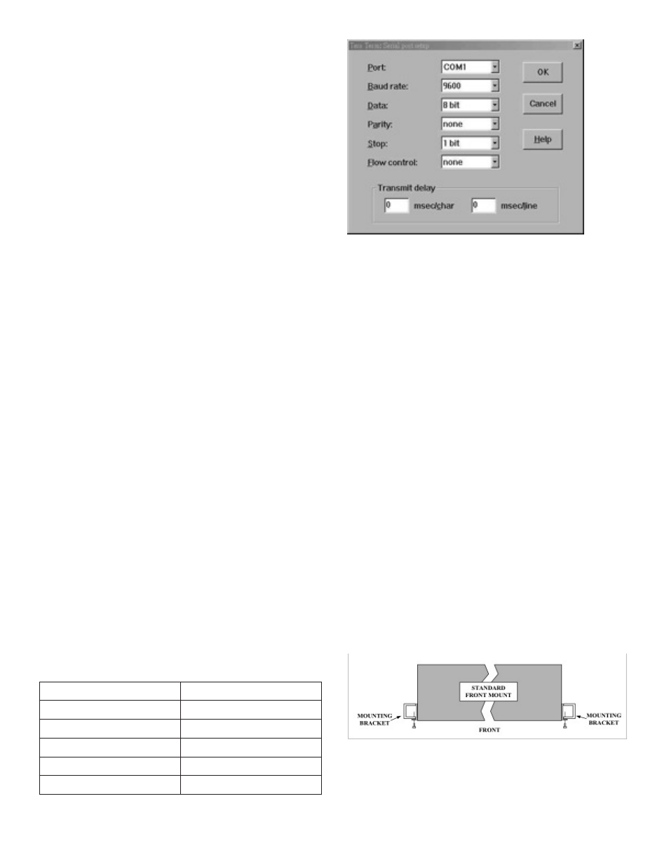
Step 5:
Connect Console cable to COM port
of a computer. Then run the terminal
program with the settings shown
below:
Table 1.2 Console Setting (EXP212, EXP224)
Baud rate
9600 bps
Data bit
8 bit
Parity
None
Stop bit
1 bit
Flow control
None
Terminal protocol
VT100
Figure 1.1 Console Setting (EXP248 only)
For EXP248: Users can also access the DSLAM
via Ethernet. The factory default in-band/out-
band IP address of the DSLAM is 10.10.10.1/24.
Users can modify the IP address by using the CLI
commands or Web Configuration Tool (refer to
section 1.3). It’s possible to access the DSLAM
with Telnet on port 23.
1.2.2 MOUNTING THE EXP212, EXP224,
OR EXP248
The position and orientation of the brackets
depends on the rack used for mounting. The
DSLAM can be front-mounted in a standard
channel rack (5-inch projection). It can be
shipped with the mounting brackets installed in
one of three mounting positions or shipped loose
(see Figure 1.2).
The mounting brackets can be rotated for use
in wall mounting. Optional adhesive feet may be
attached to the bottom of the chassis so that it
can be placed on a desk or other smooth surface.
Figure 1.2 Mounting Bracket Orientation (Top
View)