Teledex Y Series User Manual
Page 12
12
www.teledex.com
Y SERIES EXP212, EXP224, AND EXP248 USER GUIDE
3,4
5
6
7
8
GND
FAN
ERR1
FAN
ERR2
FAN
ERR3
FAN
Status
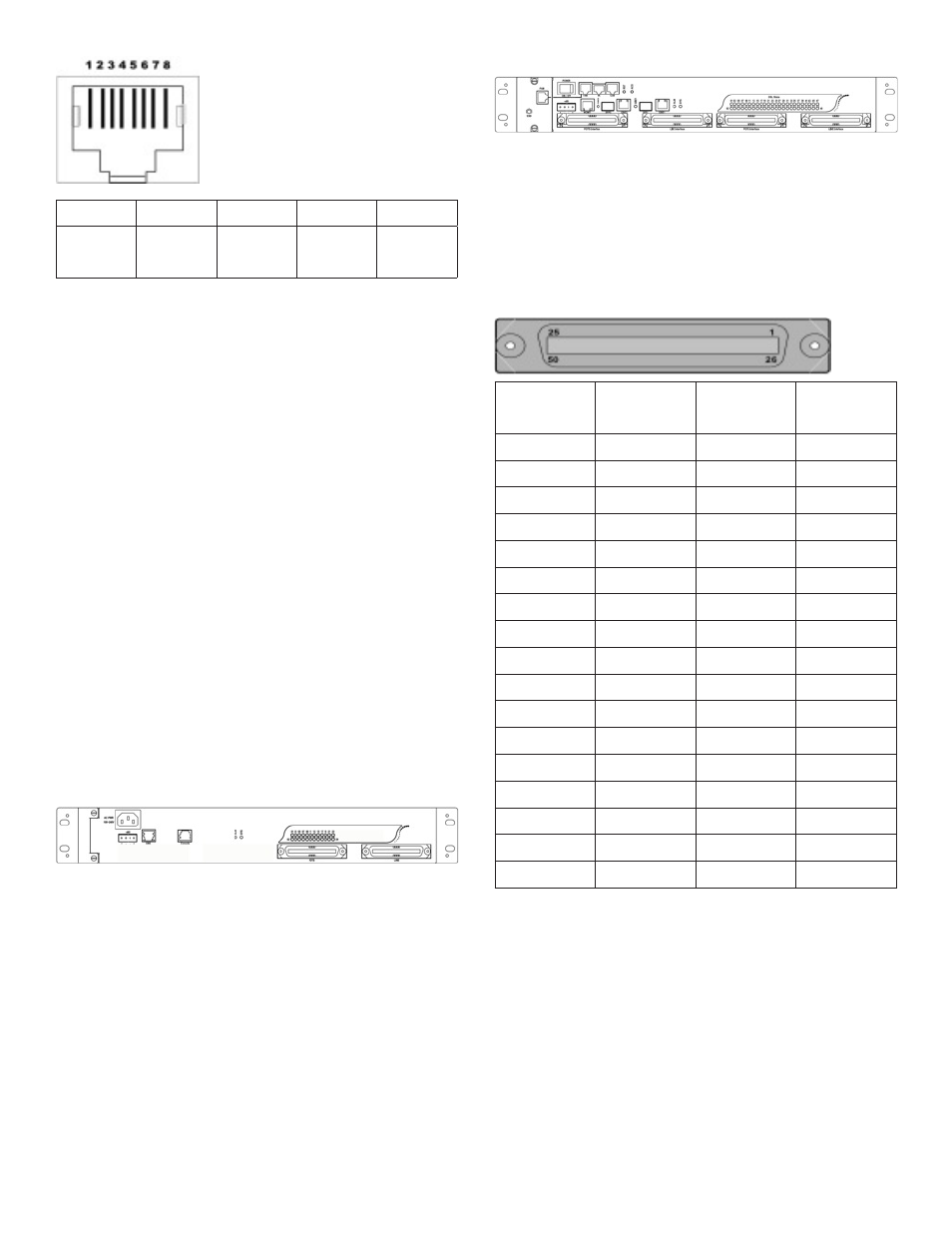
Figure 1.6 FAN Port RJ-45 Pin Assignment
1.2.5 CONNECTING THE ADSLX AND
POTS INTERFACES
The EXP212/EXP224 supports 12/24 ports ADSLx
subscribers per box. The EXP248 supports 24/48
ports ADSLx subscribers per box. There are four
RJ21 50-pin female connectors on the front panel
of the system. Two for ADSL line and two for POTS
interface.
To connect the subscriber lines, use cables with
the RJ21 50-pin male connectors. When installing,
just plug the end of a cable with connector into
the POTS or LINE interface female connector
on the front panel. The other end of the cable is
generally tied to the MDF.
The following figures shows the Line/POTS port
position of the system:
(EXP212/EXP224)
POTS port 24 ← 1 LINE port 24 ← 1
(EXP248)
POTS port 25 → 48 LINE port 25 → 48
POTS port 24 ← 1 LINE port 24 ← 1
The pin assignment of Line/POTS interface is
illustrated below (the numbers in the connector
figures below represent PIN numbers):
For port 1–24 (EXP212, EXP224, EXP248):
PIN
Number
Port
Number
PIN
Number
Port
Number
1
Tip 1
26
Ring 1
2
Tip 2
27
Ring 2
3
Tip 3
28
Ring 3
4
Tip 4
29
Ring 4
5
Tip 5
30
Ring 5
6
Tip 6
31
Ring 6
7
Tip 7
32
Ring 7
8
Tip 8
33
Ring 8
–
–
–
–
18
Tip 18
43
Ring 18
19
Tip 19
44
Ring 19
20
Tip 20
45
Ring 20
21
Tip 21
46
Ring 21
22
Tip 22
47
Ring 22
23
Tip 23
48
Ring 23
24
Tip 24
49
Ring 24
25
X
50
X