Appendix a—pin assignments, Idc punch-down connectors – Teledex Y Series User Manual
Page 19
Y SERIES EXP100 USER GUIDE
www.teledex.com
19
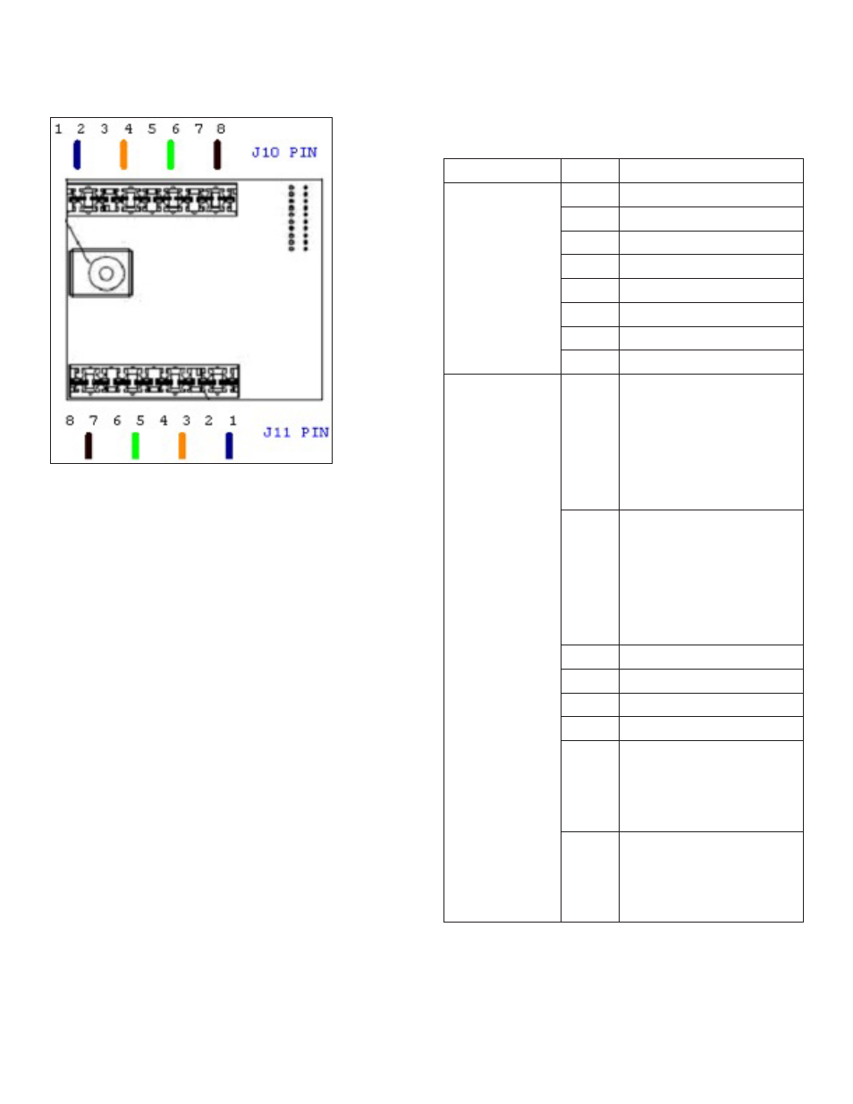
IDC Punch-Down Connectors
Connection # PIN # Descriptions
J10
1
+12Vdc Output
2
+12Vdc Output
3
Ethernet TX (+)
4
Ethernet TX (-)
5
Ethernet RX (+)
6
Ethernet RX (-)
7
Ground
8
Ground
J11
1
ADSL Line (T)/
Phone1 (T)[Bound
to PIN 4 of Tel RJ45
connector on front
panel through built-in
microfilter]
2
ADSL Line (R)/
Phone2 (R)[Bound
to PIN 5 of Tel RJ45
connector on front
panel through built-in
microfilter]
3
+12Vdc Input
4
+12Vdc Input
5
Ground
6
Ground
7
Phone2(T) [Bounded
to PIN 3 of Tel RJ45
connector on front
panel directly]
8
Phone2 [Bounded
to PIN 6 of Tel RJ45
connector on front
panel directly]
Appendix A—Pin Assignments