Step 9 attach cables – American Megatrends MAN-758 User Manual
Page 23
Chapter 1 Hardware Installation
19
Step 9 Attach Cables,
Continued
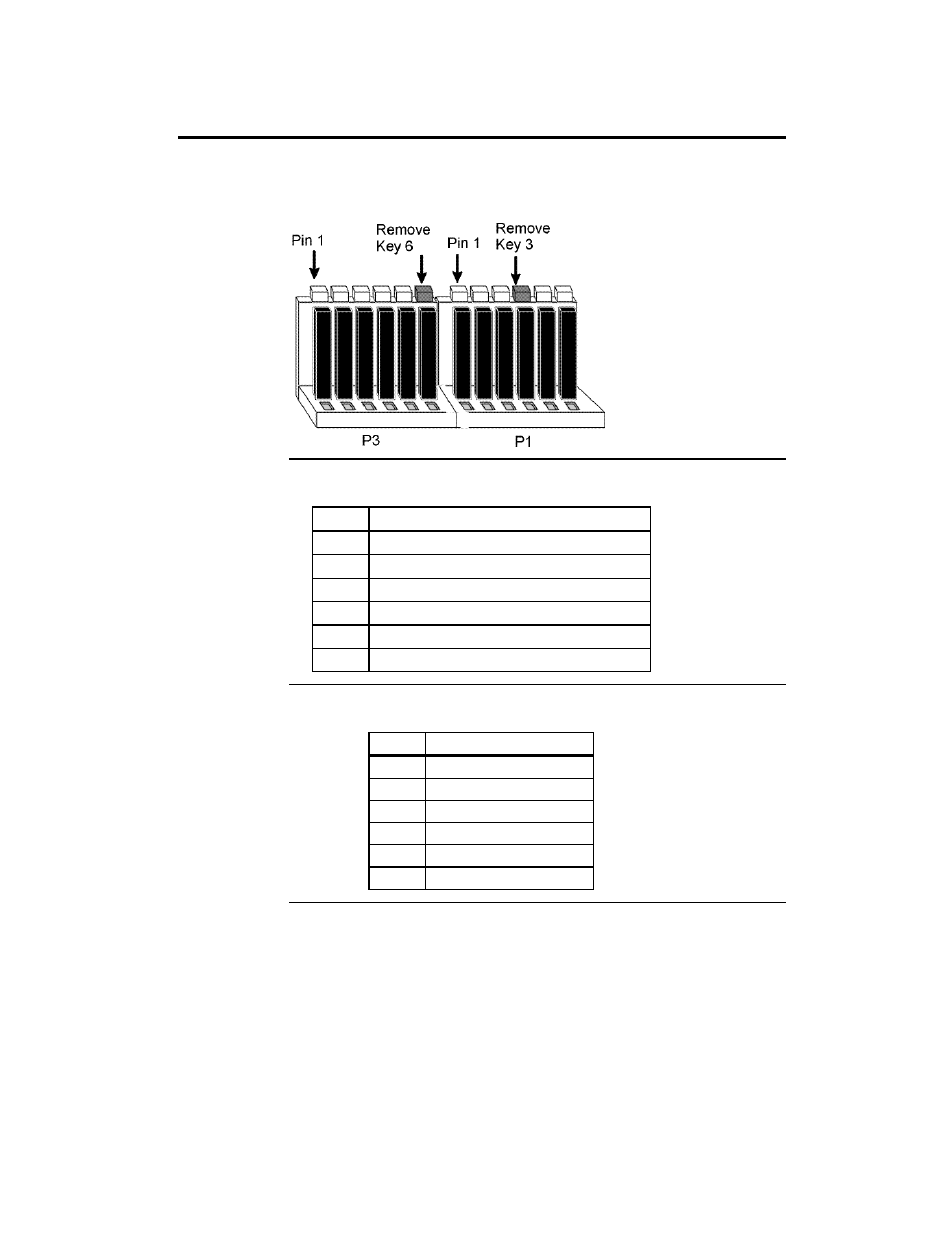
Power Connector Keys The power connectors are keyed to prevent incorrect installation. The
keys on the connector must be cut to fit on some power supplies, as shown
below.
P1 Pinout
Pin
Description
1
Power Good (Orange wire) (Not used)
2
VCC (Red wire)
3
+12 Volts (Yellow wire)
4
-12 Volts (Blue wire)
5
Ground (Black wire)
6
Ground (Black wire)
P3 Pinout
Pin
Description
1
Ground (Black wire)
2
Ground (Black wire)
3
-5 Volts (White wire)
4
VCC (Red wire)
5
VCC (Red wire)
6
VCC (Red wire)
Cont’d