Terminal descriptions, Com connector, Remote connector – Kenwood TS-990S User Manual
Page 24: Ext.at connector, Terminal descriptions -10, Com connector -10, Remote connector -10, Ext.at connector -10
1-10
1 INSTALLING AND CONNECTING THE TRANSCEIVER
TERMINAL DESCRIPTIONS
ab c d e
f g
h i
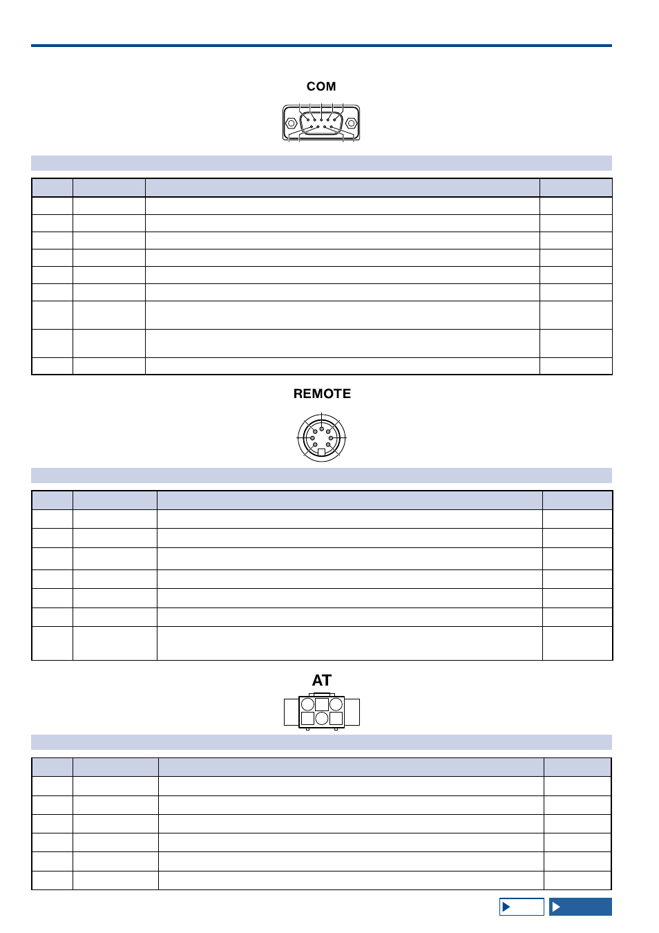
COM CONNECTOR
Pin No.
Pin Name
Function
Input/Output
1
NC
No connection
—
2
RXD
Sends the serial data to a PC.
O
3
TXD
Receives the serial data from a PC.
I
4
NC
No connection
—
5
GND
Ground
—
6
NC
No connection
—
7
RTS
Sends from a PC to the transceiver. If the PC cannot accept serial data, the PC sends the "L" state
signal to disable the transceiver from sending serial data.
I
8
CTS
Sends from the transceiver to a PC. If the transceiver cannot accept serial data, the transceiver sends
an "L" state signal to disable the PC from sending serial data.
O
9
NC
No connection
—
a
b
c
d
e
f
g
REMOTE CONNECTOR
Pin No.
Pin Name
Function
Input/Output
1
SPO
Speaker output
O
2
COM
Commonly used for an internal relay
I/O
3
SS
PTT Input
• Shorting the SS terminal to Ground starts transmission.
I
4
MKE
The make terminal for an internal relay. Shorts to the common terminal during transmission.
I/O
5
BRK
The break terminal for an internal relay Shorts to the common terminal during reception.
I/O
6
ALC
ALC input from the linear amplifier
I
7
RL
+12 V DC with a maximum of 10 mA signal is sent during TX in the HF or 50 MHz band. Following
configuration in Advanced Menus 11 and 12, it is possible to short the signal with a maximum of 10
O
a b c
d e f
EXT.AT CONNECTOR
Pin No.
Pin Name
Function
Input/Output
1
GND
Ground
—
2
TT
EXT.AT control (TTI/TTO)
I/O
3
GND
Ground
—
4
NC
No connection
—
5
TS
EXT.AT control (TSI/TSO)
I/O
6
14S
13.8 V DC source for EXT.AT
O