Notifier IPDACT-2/2UD User Manual
Page 3
DN-60408:D2 • 1/27/12 — Page 3 of 4
• Ethernet network connection (ITE-listed router/gateway).
• Although not required to meet NFPA, a small UPS is recom-
mended to provide backup power for customer-provided
router/switch (the HP3-300ULX can provide 12 VDC
backup power for small 12 volt routers drawing 500 mA or
less for over 24 hours).
• Dynamic or static IP address (dynamic addressing requires
DHCP server present on the local network. NOTE: DSL and
cable modems typically use dynamic addressing as sup-
plied by network providers).
• UDP port for IP communication with the monitoring station
(default port: 80 may be changed by central station).
• Destination IP addresses of the IP receivers where the
communicator will be sending alarms and other events (If
installed on a private Intranet, the gateway address of the
public router will be required to allow the IP card to access
the Internet and the public router at the central station).
• Panel account ID number (CID).
• Installer password (provided by the monitoring station man-
aging the IP receiver).
• Separate username and password supplied by central sta-
tion for upload/download operation. (Note: this is different
than installation password.)
MOUNTING METHODS
There are four mounting methods depending on project
requirements and panel used.
1. The IP Communicator can be mounted directly inside the
common enclosure used with the NFW-50, NFW2-100,
SFP-5UD, and SFP-10UD. When mounting inside the com-
mon enclosure the IPBRKT is used as shown on the previ-
ous page. A special polycarbonate cover is supplied that
serves to protect the unit from installed batteries.
2. The IP Communicator can be mounted in a CAB-3/4
Series Cabinet using the IP Communicator Chassis Mount-
ing Kit P/N IPCHSKIT. The IPCHSKIT mounts onto a CHS-
4/N, CHS-4L, CHS-M3, or NFS2-640 Chassis. If the sys-
tem configuration does not support the installation of the
IPCHSKIT, use the IPENC enclosure.
3. The IP Communicator can be mounted inside the small
add-on IPENC enclosure. This is typically used with previ-
ous panels that did not use the common enclosure. This will
be connected to the fire alarm panel with a short piece of
conduit.
NOTE: The 411UD application for monitoring Alarm, Trouble and
Supervisory relays of a competitive FACP requires mounting both
the 411UD and IPDACT-2UD inside the HP300ULX.
4. When more power is required, the IP Communicator can
be mounted inside the HP300ULX power supply. The power
supply should be connected to the fire alarm panel with a
short piece of conduit.
NOTE: Refer to the IP Communicator Series Installation Docu-
ment PN 53109 for additional installation information.
PROGRAMMING OPTIONS
1. Console terminal using the HyperTerminal software pro-
gram found on all Microsoft operating systems. Requires
serial programming cable PN ALMSC-119.
2. Local or remote Telnet session via Ethernet connection.
Requires either switch/hub connection or Ethernet cross-
over cable from laptop to Ethernet Port and programming
PC. The PC’s IP address must be set to the default range of
the IPDACT-2/2UD such as 192.168.0.XX.
3. Windows-based configuration software (shipped with IP
Communicator version 6.0 or higher). Version 6.0 permits
use of either Ethernet Crossover cable or Serial Cable.
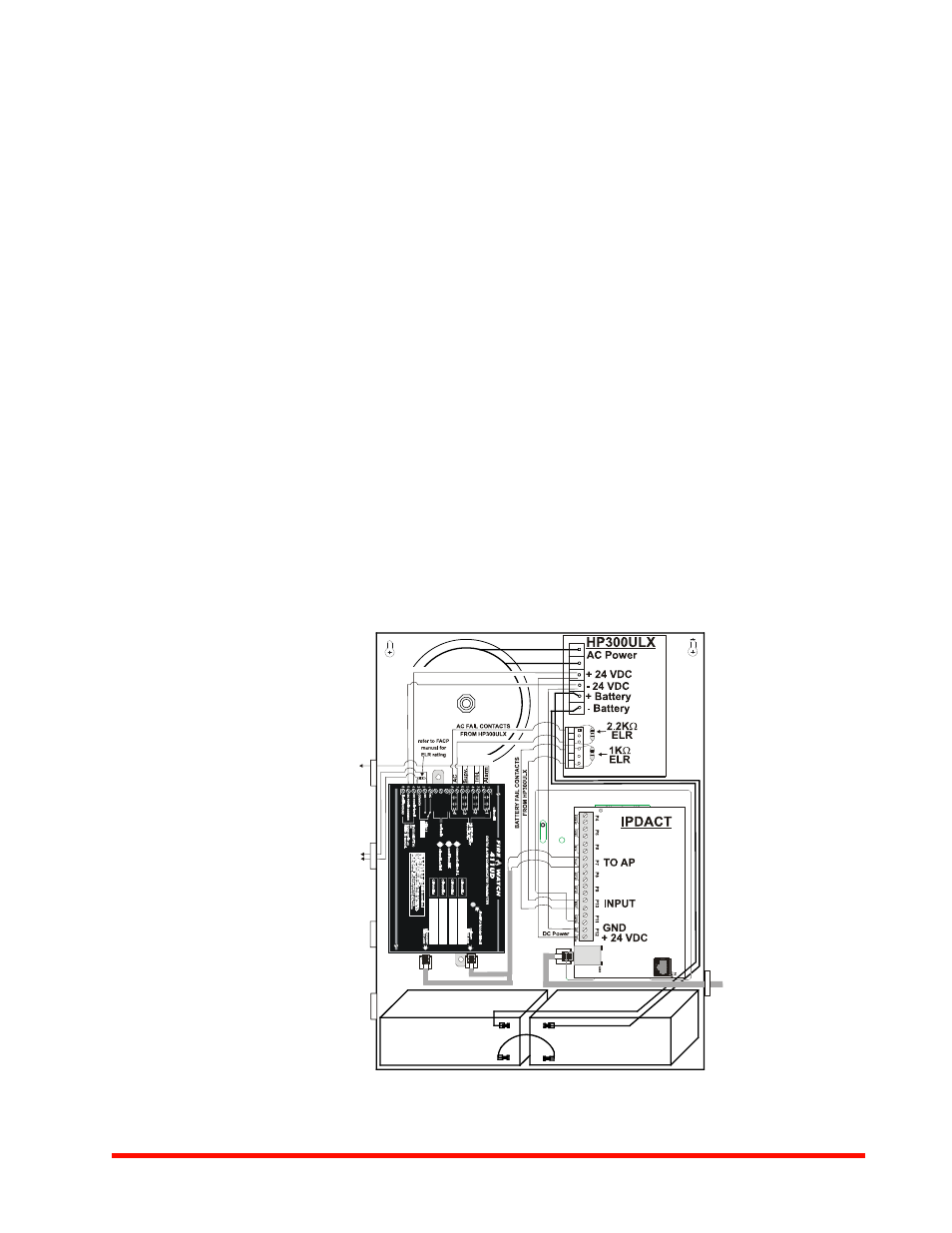
To Alarm, Trouble,
Supervisory
Output Relays
on FACP
(2.2KS ELRs at FACP)
Communicator Fault
to monitor module
on FACP SLC Loop
or in-line of
NAC on FACP
Connecting the IPDACT, 411UD and HP300ULX
HP
300UL
X
to4
11ud
2.wmf