4 power, 5 physical and environmental, Videoswitch – Videoswitch VM User Manual
Page 21: 2 remote connector, 1 dc power, 2 ac power (via main adapter provided), 1 unit dimensions, 2 packaged dimensions, 3 weights, 4 operating temperature
VM-Series Multiplexer
User Manual
20/02/2002 12:00
Videoswitch
21
VM601h.doc
17
Alarm 20
18
Alarm 10
19
Alarm 12
20
Alarm 14
21
Alarm 2
22
Alarm 4
23
Alarm 6
24
Alarm 8
25
Relay Common
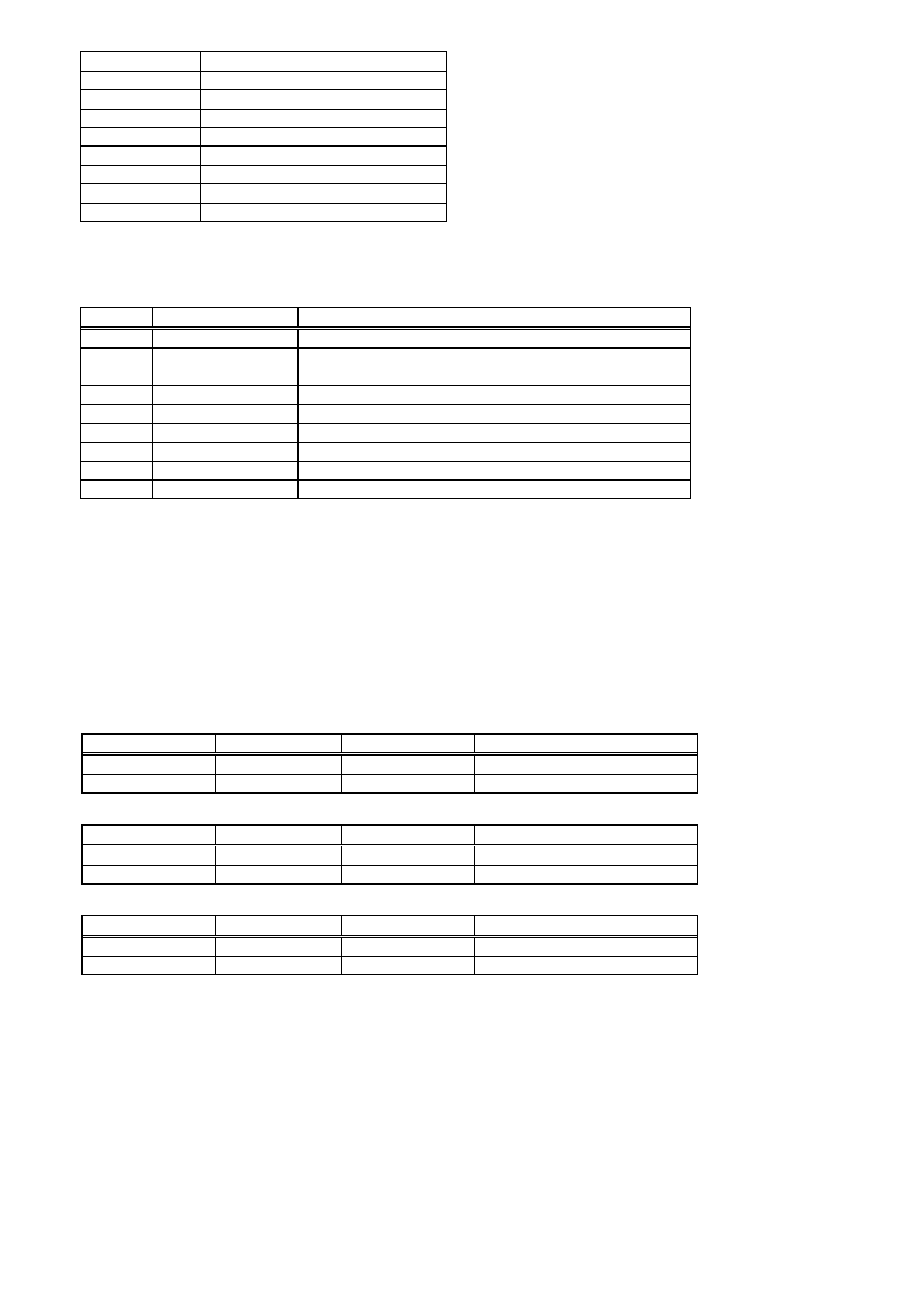
6.3.2 Remote Connector
This connector is used for connection to Remote Keyboards, Computers, Telemetry Receivers and Domes.
Mating Connector Required:
Female 9-way D-Type
Pin
Signal Type
Description
1
GND
Signal Ground (screen)
2
RS232 Output
Dome/Receiver Output
3
RS232 Input
Remote Control (Computer) Input
4
20mA Output
Telemetry Receiver Output
5
6
RS485 (A)
Dome/Receiver Output
7
RS485 (B)
Dome/Receiver Output
8
RS485 (A)
Remote Control (Keyboard) Input
9
RS485 (B)
Remote Control (Keyboard) Input
6.4 Power
6.4.1 DC Power
12VDC at 2Amps Maximum
6.4.2 AC Power (via main adapter provided)
230Vac 30W maximum
6.5 Physical and Environmental
6.5.1 Unit Dimensions
Case Style
Width
Depth
Height (including feet)
“Mini”
200 mm
257 mm
52 mm
19”
438 mm
284 mm
52 mm
6.5.2 Packaged Dimensions
Case Style
Width
Depth
Height (including feet)
“Mini”
395 mm
267 mm
120 mm
19”
582 mm
450 mm
120 mm
6.5.3 Weights
Case Style
Multiplexer
Power Supply
Packaged
“Mini”
1.6 Kg
1.4 Kg
3.6 Kg
19”
3.5 Kg
1.4 Kg
5.8 Kg
6.5.4 Operating Temperature
0 to 40 º C.
6.5.5 Storage Temperature
-20 to 60 º C
6.5.6 Humidity
5 to 95% non-condensing
6.5.7 Ventilation
Both the multiplexer and the power supply must each have adequate ventilation. Ventilation slots must not be
covered, and free air flow around the units must be permitted.