Wiring, Pv100, Valve controller – High Country Tek ProValve 100 Series User Manual
Page 24
021-PV100 Rev A
PV100 User Manual
24
Copyright © High Country Tek, Inc.
– 2013
PV100
Valve Controller
Wiring
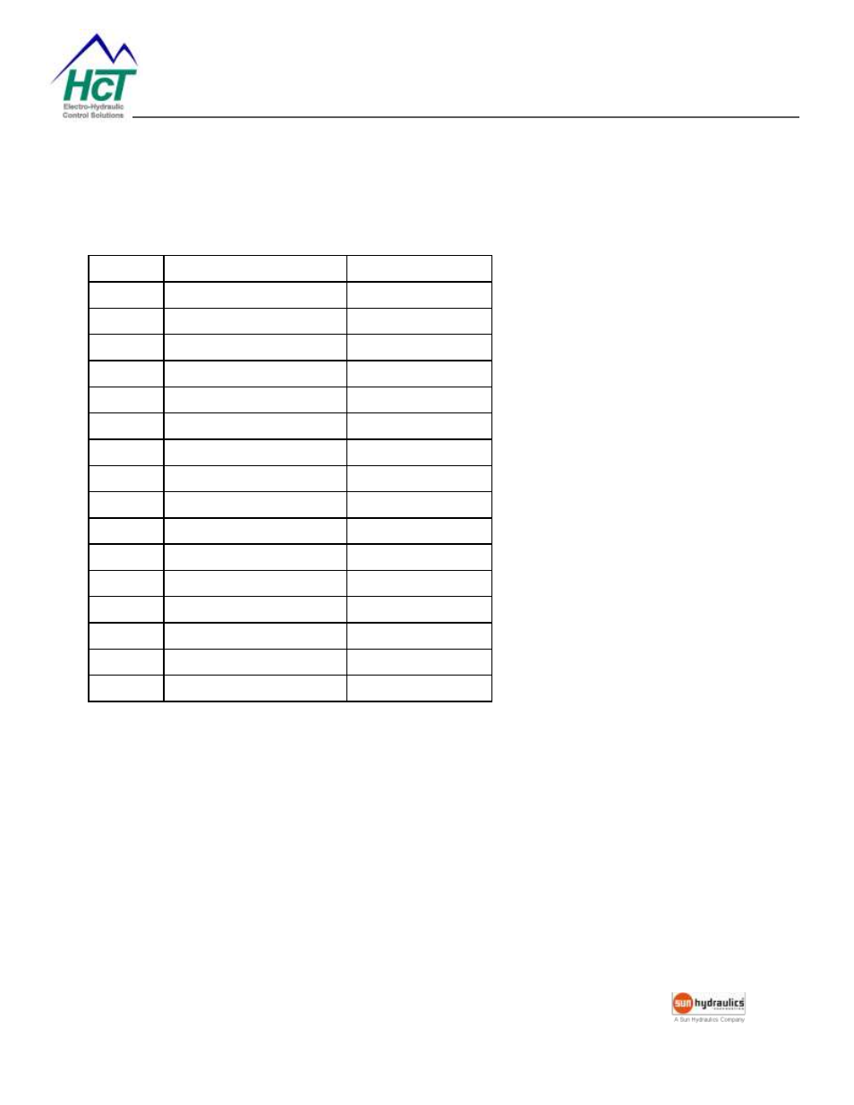
Terminal connections are listed in the table below.
Terminal
Name
Function
1
+V Supply
+24V
2
Supply Common
COM
3
+10V Reference
+10V OUT
4
-10V Reference
-10V OUT
5
Signal Input +
IN+
6
Signal Voltage Input -
INV-
7
Frame Ground
GND
8
Signal Current Input -
INI-
9
Output A
OUT A
10
Supply Common
COM
11
Output B
OUT B
12
Supply Common
COM
13
Digital Input Common
DCOM
14
Digital Input #1
DIN1
15
Digital Input #2
DIN2
16
Digital Input #3
DIN3