Physical description, User interface, Mvp-cxx-(d1) – High Country Tek MVP-C Series User Manual
Page 6: Valve controller
021-MVP-Cxx-(D1) Rev A
MVP-C-(D1) User Manual
6
Copyright © High Country Tek, Inc.
– 2013
MVP-Cxx-(D1)
Valve Controller
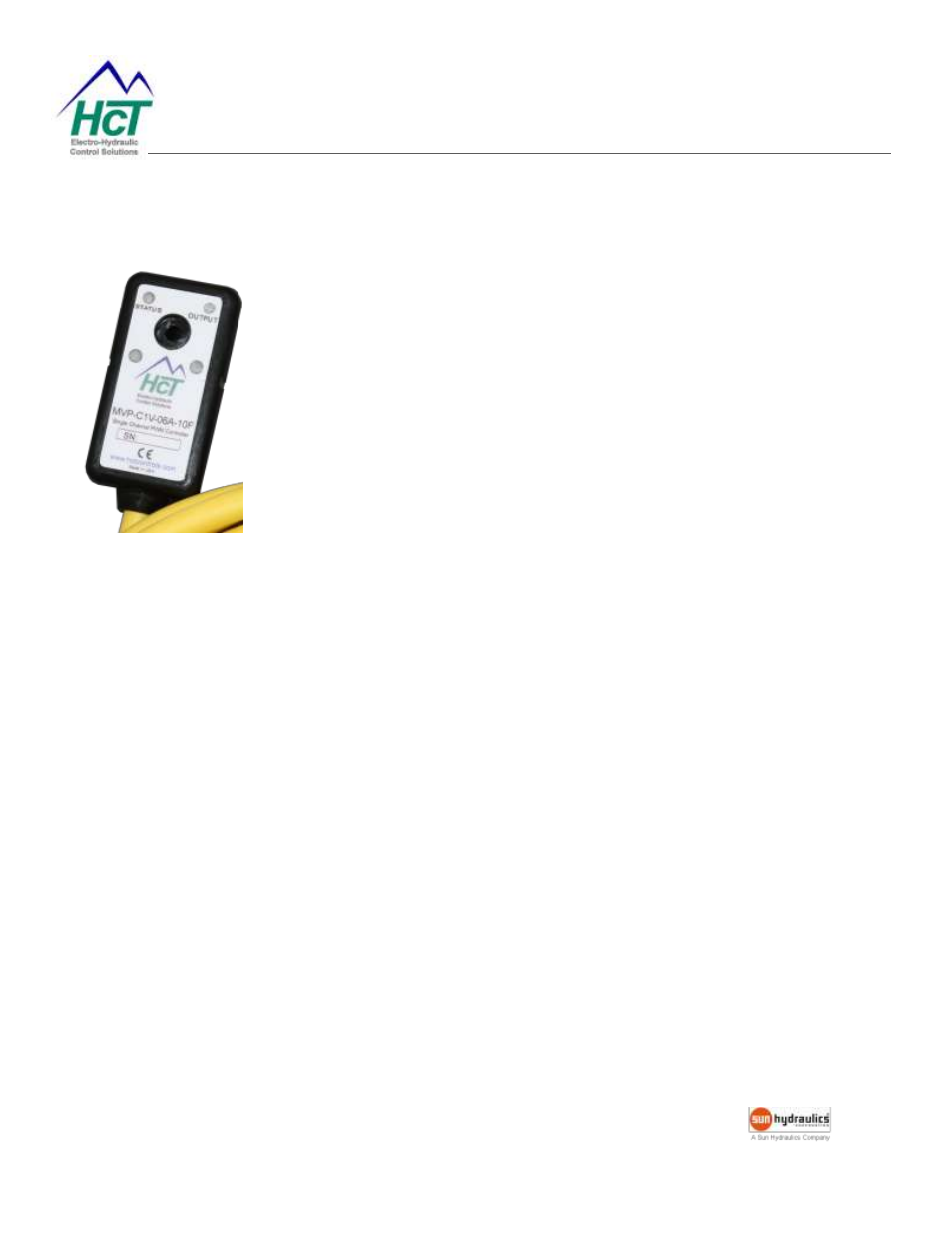
Physical Description
There are two indicator LEDs: STATUS and OUTPUT. The STATUS
LED is green when the applied voltage is within the operating range.
The OUTPUT LED is yellow and the brightness will vary with the output
current.
In the case of a fault the STATUS LED will flash red with a flash code. It
will continue to flash until clearing faults by moving the command signal
out of active range or cycling the power. See Fault Status for details.
The MVP communicates with the Graphical User Interface through an
infrared interface port to RS232. The infrared adapter clips onto the
MVPC/D1 aligning with the notches in the sides. It must be powered
when configuring the settings.
User Interface
The MVP has a number of internal settings.
Users can open the Graphical User Interface to view, make changes and save the settings in a data file which can
be uploaded to any MVP controller.
The Hand Held Interface can also be used to view and make changes, but this device does not have the capability
to save the settings in a data file. The programmer, cable and adapter are self-contained which makes the HHI a
viable alternative for field work.