Double solenoid control, Mvp-cxx-(d1), Valve controller – High Country Tek MVP-C Series User Manual
Page 20: Mvpc/d1
021-MVP-Cxx-(D1) Rev A
MVP-C-(D1) User Manual
20
Copyright © High Country Tek, Inc.
– 2013
MVP-Cxx-(D1)
Valve Controller
Double Solenoid Control
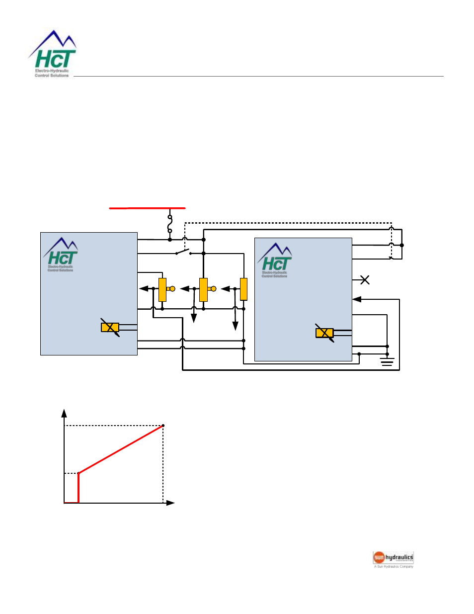
Two MVPs can drive a double solenoid valve with a signal of 0-5VDC, or 0-10VDC, or 4-20mA.
A selector switch determines which solenoid is activated. If enable switch is not used, set MVP #1 to be Mode 1,
MVP #2 to be Mode 1. If enable switch is used, set MVP #1 to be Mode 3, MVP #2 to be Mode 3.
Set the dither and output settings according to the valve specifications.
FUSE
+V Power Input
9 - 28VDC
+V = Enabled
Brown PWR +
MVPC/D1
Electronic Valve
Controller
White Enable
GRN/YEL
+5VDC @ 2mA
0-5VDC
Red Ref. Out
BLK Analog I/P
Blue GND
V
D
C
I/
P
m
A
I/
P
0-10VDC
V
D
C
I/
P
4-20mA
Connector GND
Screen
+V = Enabled
Brown PWR +
MVPC/D1
Electronic Valve
Controller
White Enable
GRN/YEL
Prop. PWM
(Sourcing)
+5VDC @ 2mA
0-5, or 0-10, or 4-20
Red Ref. Out
BLK Analog I/P
Blue GND
Connector GND
Screen
Prop. PWM
(Sourcing)
min
Command
Input
Output Current for both coils
0
max
min
max