Hydraulic fan system controller : hfs - 2 – High Country Tek HFS-2Q User Manual
Page 29
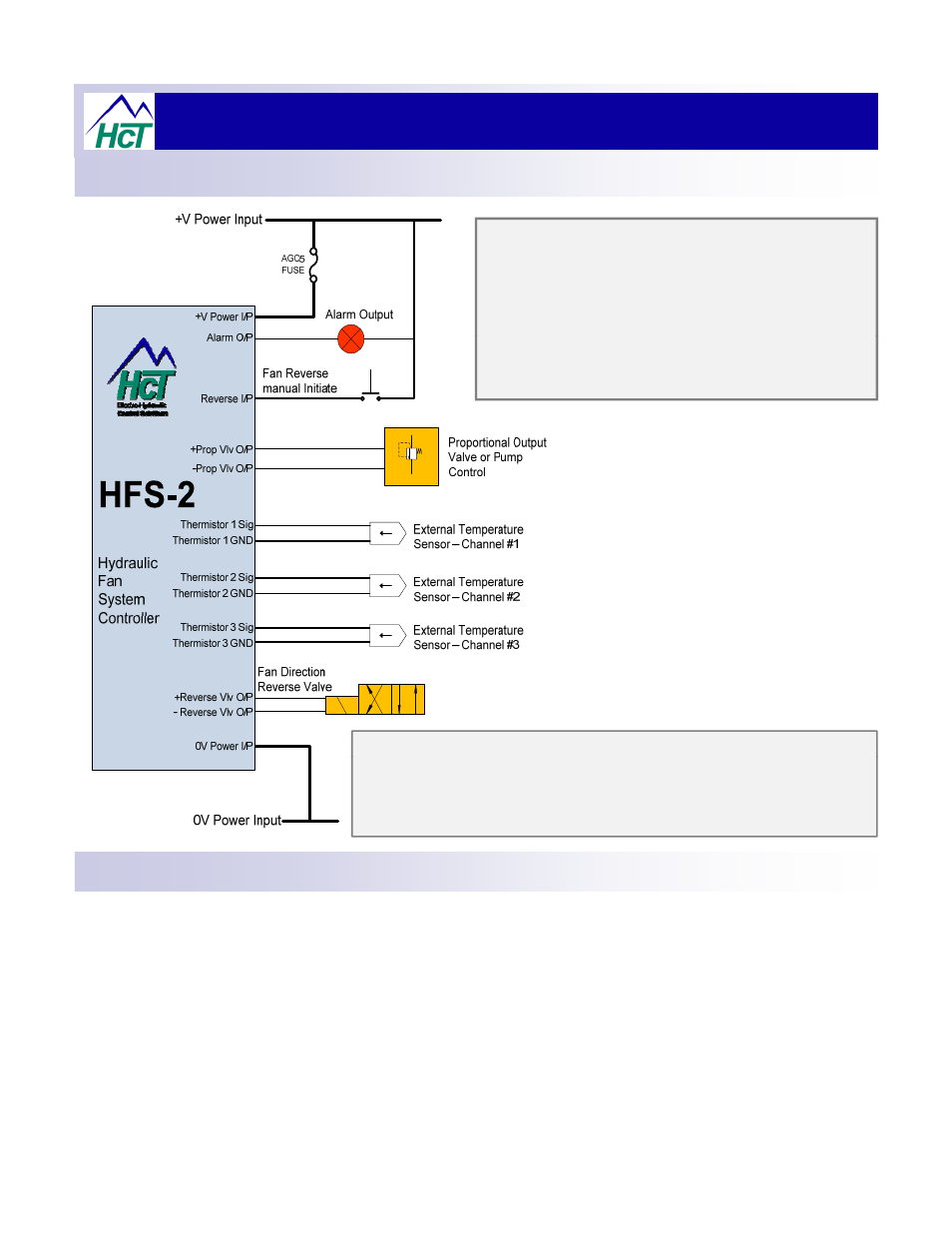
Hydraulic Fan System Controller : HFS - 2
Electrical Connection Information:
Alarm output shown driving a simple lamp to indicate fault /
error condition has occurred.
This same connection circuit can be used with a relay or
solenoid
( Always use suitable’ Flyback’ or suppression diode
here ) to facilitate system integration as required such that
engine shutdown could be initiated if the fault continued un
cleared.
The maximum switching current of this output is 3.3amps at
supply voltage.
•
Always observe safety when adjusting this controller – fan may start to
rotate without warning.
•
Always fit power supply fuse ( as shown ) externally to controller.
•
Ensure two wires are used for every temperature sensor.
•
Use software to make any changes to system configuration and/or options.
Fan Max Speed Manual Override:
The system using the ‘Reverse acting’ proportional pressure relief valve ( as shown in this manual ) is designed to default to full
fan speed in the event of a power supply, fuse or connection failure.
The user may also initiate full fan speed regardless of the controller settings by simply turning the unit ‘ OFF ‘ via a simple
switch.
This option can be used on initial commissioning or during service to prove the hydraulic continuity circuit if required.
Once the unit is switched back ‘ ON ‘ , the controller will re-initialize and the real time temperature measurements in each zone
used once again to dictate the ideal fan speed
29
used once again to dictate the ideal fan speed.
NOTE:- If the unit power supply is turned ‘ OFF ‘ to force fan full speed, the ‘Purge’ function, diagnostic indicators and alarm
output will not operate until power is restored to the unit.