5 connection, 5 connection -19 – ARI Armaturen CONA control EN User Manual
Page 19
Rev. 0040807014 1614
Page 2-19
Operating and Installation Instructions
CONA
®
-control
5.5.5 Connection
In the delivery condition the sensor is mounted in the test chamber and connected with
cable lugs in the measuring amplifier. The plug-in contacts of the measuring amplifier are
marked with the same colours as the sensor wires.
Standard version / Measuring amplifier iwth relay card:
The cover must be unscrewed in order to connect the power supply. Feed the cable through
the gland, then connect the 30 V DC power supply to the "+" and "-" screw-type terminals
according to the wire polarity (refer to Fig. 14).
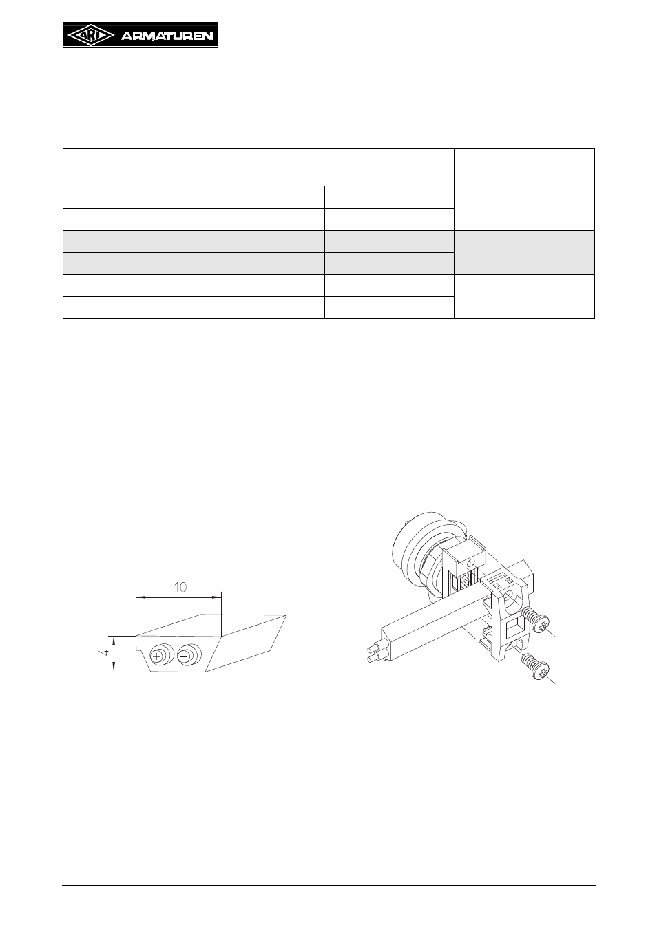
Measuring amplifier with bus card:
The measuring amplifier with a bus card has a special gland for the AS-i bus cable. There is
consequently no need to open the amplifier cover.
Loosen the bracket of the cable gland with the two screws. Insert the AS-i cable into the
gland according to the form and screw the bracket back on again (refer to Fig. 15).
Designation on
card
Cable colour
bl/wt
Blue / white
Blau / Weiß
Heating
wt
White
Weiß
bl
Blue
Blau
Temperature sensor 1
rd
Red
Rot
bl
Blue
Blau
Temperature sensor 2
rd/bl
Red / blue
Rot / Blau
Fig. 14
Fig. 15