3 bolt-on test chamber, 4 connecting and laying the as-interface circuit – ARI Armaturen CONA control EN User Manual
Page 15
Rev. 0040807014 1614
Page 2-15
Operating and Installation Instructions
CONA
®
-control
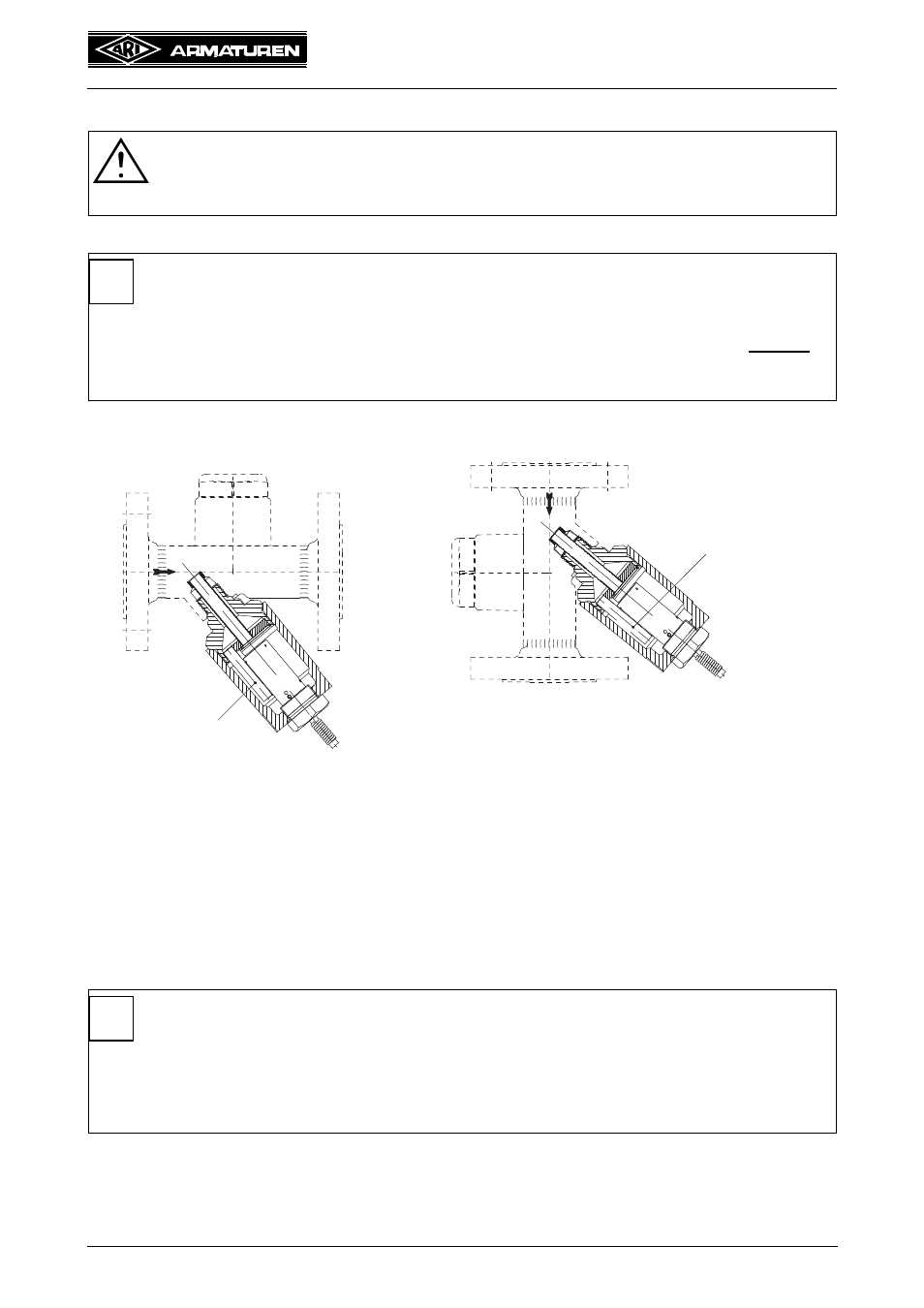
5.3 Bolt-on test chamber
Fig. 10
By unscrewing the sensor, the installation position can be inspected and if necessary
corrected. The outlet pipes are just fixed by a circlip and can be turned simply to the right
position.
5.4 Connecting and laying the AS-Interface circuit
In principle, flat and round cables can be combined. The prevailing external conditions
determine whether the cables should be made of rubber (max. 85°C), TPE (max. 105°C),
PVC (max. 90°C) or PUR (max. 85°C).
Please heed the following points when laying the AS-Interface:
- Always use the yellow, shaped AS-Interface if possible (brown for "+" and blue for "-").
ATTENTION !
- Make sure the inlet and outlet are shut off prior to all work on the steam trap.
The device must be de-pressurised and cooled down!
NOTE !
Note the installation position!
- Test chamber pointing diagonally downwards.
- For correct function of the bolt-on test chamber, the outlet pipes must always
be at the lowest point of the body.
Otherwise steam flow can not be detected.
Vertical installation
Horizontal installation
NOTE !
- Use a special AS-Interface cable with reverse polarity protection.
- Max. cable length: 100 m.
- If 100 m is too short, several manufacturers such as Bihl&Wiedemann or
Pepperl&Fuchs today offer solutions up to 1000 m, for example using
repeaters, passive bus terminating resistors or tuners.
i
Outlet pipe
Outlet pipe
i