Specifications (cont’d), Overview, Block diagram – Red Lion IFMA User Manual
Page 2
2
10
12
AC VERSION
ISOLATED
OUTPUT
SUPPLY
SUPPLY
PROCESS
INPUT
INPUT
PROCESS
SUPPLY
SUPPLY
OUTPUT
ISOLATED
DC VERSION
12
10
INPUT
(GREEN)
OUTPUT
(RED)
+5V
INPUT LED
OUTPUT LED
S4
S5
S6
S7
MODE
CFG2
CFG1
CFG0
BCD
SWITCH
BCD
INPUTS
PUSH
BUTTON
BUTTON
INPUT
DIP
SWITCH
INPUTS
PROCESS
CIRCUITRY
8
7
9
S3
SINK
3.9K
1K
S1
SRC
+
-
10.0K
0.1µf
100pf
33.2K
8.06K
54.9K
392K
10K
S2
LOGIC
+12V
+5V
+5V
+12V
+12V
INPUT
SIGNAL
9 to 32 VDC
+5V
+5V
+5V
200K
0.1µf
-
+
47.5K
+
-
3
4
1
6
10.0K
200K
10.0K
24.3Ω
1.47K
O
V+
I+
I-
V-
Vref
Vout
OUTPUT
DAC
ISOLATED ANALOG OUTPUT
0.1µf
18Vo
SUPPLY
12 VDC
SIGNAL
INPUT
COMMON
OUTPUT
DAC
CONTROL
LINES
SENSOR
INPUT
PUSH
DC
SWITCHING
CIRCUIT
(60 mA)
(AC VERSION ONLY)
+
-
85 to 250
VAC
AC
POWER
AC
SWITCHING
CIRCUIT
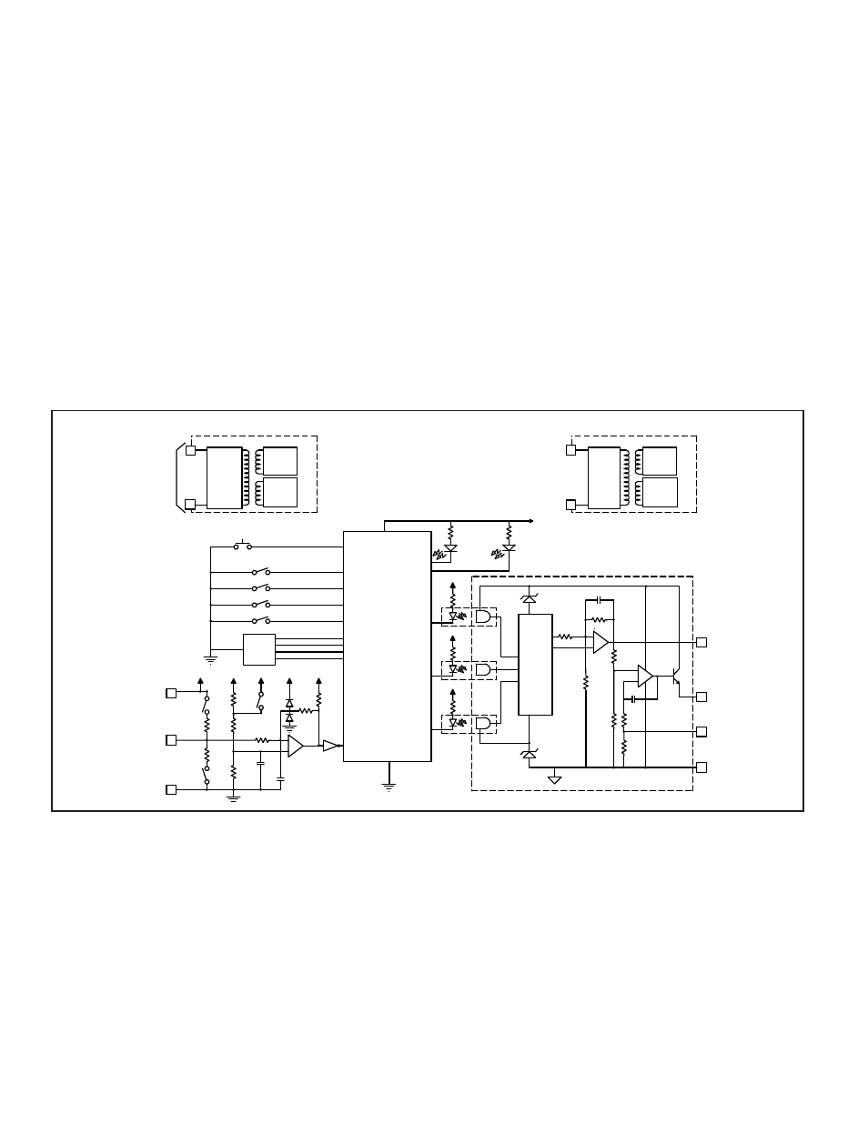
BLOCK DIAGRAM
SPECIFICATIONS (Cont’d)
10. RESPONSE TIME: 5 msec +1 period to 10 sec +1 period; user selectable
11. INPUT IMPEDANCE: 33 K
min. with the sink and source DIP switches
in the OFF position (See Block Diagram).
12. INPUT AND POWER CONNECTIONS: Screw in terminal blocks.
13. ISOLATION BREAKDOWN VOLTAGE (Dielectric Withstand): 2200
V between power & input, and power & output; 500 V between input &
output for 1 minute.
14. CERTIFICATIONS AND COMPLIANCES:
SAFETY
UL Recognized Component, File #E137808, UL508, CSA C22.2 No. 14
Recognized to U.S. and Canadian requirements under the Component
Recognition Program of Underwriters Laboratories, Inc.
IECEE CB Scheme Test Report # 97ME50135-042297
Issued by Underwriters Laboratories, Inc.
IEC 61010-1, EN 61010-1: Safety requirements for electrical equipment
for measurement, control, and laboratory use, Part 1.
EMC EMISSIONS:
Meets EN 50081-2: Industrial Environment.
CISPR 11 Radiated and conducted emissions
EMC IMMUNITY:
Meets EN 50082-2: Industrial Environment.
ENV 50140 - Radio-frequency radiated electromagnetic field
1
ENV 50141 - Radio-frequency conducted electromagnetic field
EN 61000-4-2 - Electrostatic discharge (ESD)
2
EN 61000-4-4 - Electrical fast transient/burst (EFT)
EN 61000-4-8 - Power frequency magnetic field
Notes:
1. For operation without loss of performance:
Unit is mounted on a rail in a metal enclosure (Buckeye SM7013-0 or
equivalent) and I/O cables are routed in metal conduit connected to
earth ground.
2. This device was designed for installation in an enclosure. To avoid
electrostatic discharge, precautions should be taken when the device is
mounted outside an enclosure. When working in an enclosure (ex. making
adjustments, setting switches, etc.) typical anti-static precautions should
be observed before touching the unit.
Refer to the EMC Installation Guidelines section of this bulletin for
additional information.
15. ENVIRONMENTAL CONDITIONS:
Operating Temperature: 0 to 50°C
Storage Temperature: -40 to 80°C
Operating and Storage Humidity: 85% max. (non-condensing) from 0°C
to 50°C.
Vibration according to IEC 68-2-6: Operational 5 to 150 Hz, in X, Y, Z
direction for 1.5 hours, 3 g’s.
Shock according to IEC 68-2-27: Operational 30 g’s, 11 msec in 3 directions.
Altitude: Up to 2000 meters
16. CONSTRUCTION: Case body is black, high impact plastic. Installation
Category II, Pollution Degree 2
17. WEIGHT: 6 oz. (0.17 Kg)
OVERVIEW
The Model IFMA continuously monitors a frequency input and outputs a
voltage or current signal in proportion to the input signal. The output is accurate
to ±0.1% of full scale for Operating Modes 2, 3, and 4. Operating Mode 1 is
accurate to ±0.2% of full scale. The green Input LED blinks at the rate of the
input frequency. At about 100 Hz, the Input LED will appear to be solid on. At
very low frequencies, the Input LED blinks slowly and may also appear to be
solid on. A loss of signal may also cause the Input LED to remain on, depending
on the DIP switch set-up. In this case, the red LED also turns on.
The Minimum Response Time parameter sets the minimum update time of the
output. The actual response time is the Minimum Response Time plus up to one
full period of the input signal. The IFMA counts the negative edges occurring
during the update time period, and computes the average frequency value for that
time. This action filters out any high frequency jitter that may be present in the
input signal. The longer the Minimum Response Time, the more filtering occurs.
The Maximum Response Time parameter sets the Low Frequency Cut-out
response time for the unit. If a new edge is not detected within the time specified
by the Maximum Response Time setting, the unit sets the output to the
existing Low Frequency Cut-out Value setting depending on the selected range
and calibration setting.
The unit also indicates Low Frequency Cut-out by turning ON the output
LED. The Maximum Response Time can be set shorter than the Minimum
Response Time. In this case, as long as the input signal period is shorter than the
Maximum Response Time, the unit continues to indicate the input frequency at
its output. But, if the input period at any time exceeds the Maximum Response
Time, the unit immediately takes the output to the Low Frequency Cut-out
Value, regardless of the Minimum Response Time setting.
The IFMA is calibrated at the factory for all of the selected ranges. However,
the user can adjust the minimum calibration to any value less than the Full Scale
value, and the Full Scale value to any value greater than the minimum value. If
the minimum and full scale values are brought closer together, the accuracy of the
unit decreases proportionate to the decreased range of the unit (See Calibration).