Controller programming, Unprotected parameter mode, Protected parameter mode – Red Lion PSC User Manual
Page 5: Hidden functions mode, Output variations without rs485 option, Output variations with rs485 option, Output modules
5
CONTROLLER PROGRAMMING
The model PSC has been designed to reduce the operator interaction with the
controller while still maintaining a high degree of control accuracy and user
flexibility. Front panel program disable allows all of the controller’s set-ups to be
locked-out from further operator intervention after the initial parameter set-up.
The programming of the controller is divided into four sections:
Hidden Mode
Protected Mode
Unprotected Mode
Configuration Mode
These four programming modes allow the controller to adapt to any required
user-interface level.
UNPROTECTED PARAMETER MODE
The unprotected mode is accessible when program disable is inactive or when
the proper access code number from the protected mode is entered. Only from
this mode can the configuration modes be accessed.
“SP”
- Enter setpoint
*
“OPOF” - Enter %output power offset
*
“OP”
- Enter output power
*
“ProP”
- Enter proportional band
“Intt”
- Enter integral time
*
“dErt”
- Enter derivative time
*
“AL-1”
- Enter value for alarm #1
*
“AL-2”
- Enter value for alarm #2
*
“CNFP” - Select basic configuration module
“End”
- Return to normal display mode
PROTECTED PARAMETER MODE
*
The protected mode is accessible when program disable is active, also this
mode prevents access to the configuration modes without the proper access code
number. Only the parameters that are selected in the configuration 3 parameter
lock-outs section can be accessed.
“ProP”
- Enter proportional band
“Intt”
- Enter integral time
“dErt”
- Enter derivative time
“AL-1”
- Enter value for alarm #1
“AL-2”
- Enter value for alarm #2
“CodE” - Enter access value to unprotected mode
*
These parameters may not appear due to option configuration or other
programming.
HIDDEN FUNCTIONS MODE
*
The hidden mode is accessible from the normal operating mode by holding
the PAR button for 3 seconds. The five functions in this mode may be locked-out
individually in configuration 3 parameter lock-outs section.
“ CP”
- Invoke control point x
“Prun”
- Control ramp/hold profile state
“trnF”
- Transfer between automatic (PID) control and Manual control
“tUNE”
- Invoke/Cancel PID auto-tune
“ALrS”
- Reset latched alarms
*
These parameters may not appear due to option configuration or other
programming.
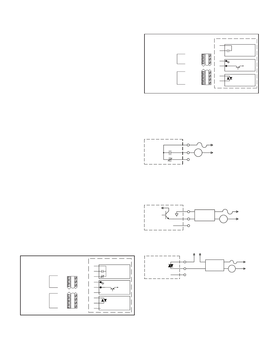
OUTPUT VARIATIONS WITHOUT RS485 OPTION
The Dual Alarm or the Secondary with Alarm output, without the RS485
option, has independent outputs. Therefore, the secondary output and/or alarm
output(s) can be installed with any combination of output modules.
OUTPUT VARIATIONS WITH RS485 OPTION
The Dual Alarm or the Secondary with Alarm output, with RS485 option,
does not have independent outputs. In this case, the secondary output and/or
alarm output(s) must have the same type of output modules installed since they
share the common terminal.
OUTPUT MODULES
Units equipped with RS485 option must have the Dual Alarm or Secondary
w/alarm options fitted with the same type of output modules. The controller’s
main output (OP1) can be fitted with any output module. Output modules are
shipped separately and must be installed by the user.
TYPICAL CONNECTIONS
Relay:
Type: Form -C (Form-A with RS485 option only)
Rating: 5 Amps @ 120/240 VAC or 28 VDC (resistive load), 1/8 HP @ 120
VAC (inductive).
Life Expectancy: 100,000 cycles at maximum load rating.
(Decreasing load and/or increasing cycle time, increases life expectancy).
Logic/SSR Drive: can drive multiple SSR Power Units.
Type: Non-isolated switched DC, 12 VDC typical.
Drive: 45 mA max.
Triac:
Type: Isolated, Zero Crossing Detection.
Rating:
Voltage: 120/240 VAC.
Max. Load Current: 1 Amp @ 35°C
0.75 Amp @ 50°C
Min. Load Current: 10 mA
Off State Leakage Current: 7 mA max @ 60 Hz.
Operating Frequency: 20 to 500 Hz.
Protection: Internal Transient Snubber, Fused.
WITHOUT RS-485 OPTION
SECONDARY W/ALARM OPTION
DUAL ALARM OR
ALARM 1
OPTION
N/C
AL1-A
AL1-B
AL1-C
13
14
15
16
ALARM 2 OR
SECONDARY
OUTPUT 2
OPTION
AL2/OP2-A
AL2/OP2-B
AL2/OP2-C
1
2
3
C
B
A
DO NOT CONNECT
TRIAC
(ISOLATED)
1A @ 240VAC
LOGIC/SSR DRIVE
DO NOT CONNECT
+
-
(RESISTIVE LOAD)
5A @ 240VAC
RELAY
A
B
C
C
B
A
OUTPUT MODULES
+12VDC
NOT
ISOLATED
WITH RS-485 OPTION
SECONDARY W/ALARM OPTION
DUAL ALARM OR
RS-485
OPTION
TX/RX(+)
TX/RX(-)
TX EN.
RS-485 COMM.
13
14
15
16
OR
ALARM 1 WITH
SECONDARY OUTPUT 2
OPTION
AL/OP2 COMM.-A
AL2/OP2-B
AL1-B
1
2
3
ALARM 1 AND ALARM 2
OUTPUT MODULES
A
B
B
A
RELAY
5A @ 240VAC
(RESISTIVE LOAD)
1A @ 240VAC
(ISOLATED)
TRIAC
A
B
ISOLATED
NOT
+12VDC
-
+
LOGIC/SSR DRIVE
LOAD
A
B
C
POWER
5 AMPS
AT
240
VAC
RELAY
MODULE
DO NOT CONNECT
SSR
POWER
UNIT
LOAD
4
3
1
2
A
B
C
POWER
+12VDC
UNREG.
+
-
NOT
ISOLATED
LOGIC/SSR DRIVE
MODULE
POWER
120VAC
AT
1 AMP
120/240VAC
ISOLATED
A
B
C
RELAY OR
DEVICE
TRIAC
LOAD
DO NOT CONNECT
TRIAC MODULE