Block diagram – Red Lion CSPID User Manual
Page 3
3
11. ALARMS:
Modes:
Manual
Absolute High Acting
Absolute Low Acting
Deviation High Acting
Deviation Low Acting
Inside Band Acting
Outside Band Acting
Reset Action: Programmable; automatic or latched
Standby Mode: Programmable; enable or disable
Hysteresis: Programmable
Sensor Fail Response: Upscale
12. ANALOG DC OUTPUT (optional, CSPID1 only):
Selectable/programmable for 0-10 VDC, 0-20 mA, or 4-20 mA
Resolution:
Voltage: 500 µV
Current: 1 µA
Accuracy:
0.1% of full scale (18 to 28 °C)
0.2% of full scale (0 to 50 °C)
Update Time: 0.0 to 60.0 sec
Compliance (for current output only): 500 Ω max.
Minimum load (voltage output only): 10 KΩ min.
Outputs are independently jumper selectable for either 10 V or 20 mA. The
output range may be field calibrated to yield approximate 10% overrange and
a small underrange (negative) signal.
13. HEATER CURRENT MONITOR INPUT (optional):
Type: 300 V max, 50 A max. Single phase, full wave monitoring of load
currents
Input: 100 mA max. input for use with external current transformers
Input Resistance: 5 Ω
Accuracy: ±3.0% full scale, 5 to 100% of range
Frequency: 50 to 400 Hz
Minimum output on time for break alarm: 350 msec
14. ENVIRONMENTAL CONDITIONS:
Operating Temperature Range: 0 to +50 °C
Storage Temperature Range: -40 to +85 °C
Operating and Storage Humidity: 85% max relative humidity, non-
condensing, from 0 to +50°C
Vibration According to IEC 68-2-6: Operational 10 to 150 Hz, 0.075 mm
amplitude in X, Y, Z direction 1 g.
Shock According to IEC 68-2-27: Operational 25 g (10 g relay), 11 msec in
3 directions.
Altitude: Up to 2000 meters
15. CERTIFICATIONS AND COMPLIANCES:
SAFETY
Check each module’s specifications to determine system compliance.
UL Listed, File #E302106, UL508, CSA 22.2 No. 14-M05 and File #E179259,
UL61010-1, CAN/CSA-C22.2 No. 61010-1; and File #E317425, ANSI/ISA
12.12.01-2007, CSA 22.2 No. 213-M1987
LISTED by Und. Lab. Inc. to U.S. and Canadian safety standards
IEC 61010-1, EN 61010-1: Safety requirements for electrical equipment
for measurement, control, and laboratory use, Part 1.
ELECTROMAGNETIC COMPATIBILITY
Emissions and Immunity to EN 61326: 2006: Electrical Equipment for
Measurement, Control and Laboratory use.
Immunity to Industrial Locations:
Electrostatic discharge
EN 61000-4-2 Criterion B
4kV contact discharge
8kV air discharge
Electromagnetic RF fields
EN 61000-4-3 Criterion B
3
10V/m (80 MHz to 1 GHz)
3 V/m (1.4 GHz to 2 GHz)
1 V/m (2 GHz to 2.7 GHz)
Fast transients (burst)
EN 61000-4-4 Criterion B
power 2kV
I/O signal 1kV
I/O signal connected to power 2kV
Surge
EN 61000-4-5 Criterion B
power 1 kV L to L, 2 kV L to G
signal 1 kV
RF conducted interference EN 61000-4-6 Criterion A
3 Vrms
Emissions:
Emissions
EN55011
Class A
Notes:
1. Criterion A: Normal operation within specified limits.
2. Criterion B: Temporary loss of performance from which the unit self-
recovers.
3. The module’s analog input and/or output signals may deviate during
disturbance but self-recover when disturbance is removed.
4. Power supplied from backplane via Master Module.
16. CONSTRUCTION: Case body is burgundy high impact plastic. For indoor
use only. Installation Category II, Pollution Degree 2.
17. CONNECTIONS: Removable wire clamp screw terminal blocks.
Wire Gage: 28-16 AWG terminal gage wire
Torque: 1.96-2.23 inch/lbs (0.22-0.25 N-m)
18. MOUNTING: Snaps on to standard DIN style top hat (T) profile mounting
rails according to EN50022 -35 x 7.5 and -35 x 15.
19. WEIGHT: CSPID1: 7 oz (198.4 g)
CSPID2: 7 oz (198.4 g)
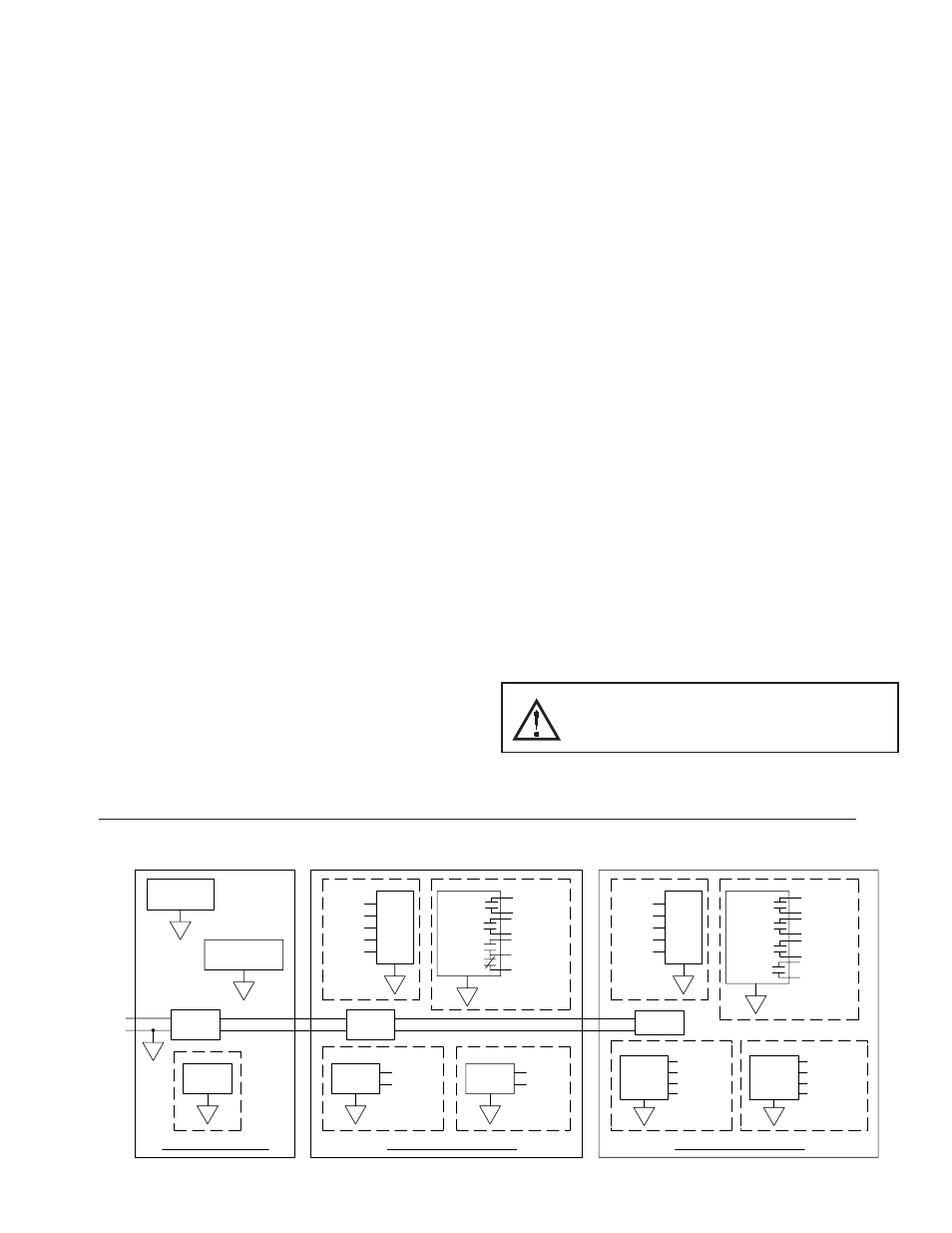
PORT 3
ETHERNET
B
ISOLATED
A
POWER
SUPPLY
+
-
24VDC
CSMSTR - MASTER
CSPID1 - PID MODULE
PORT 2
A
COMMUNICATIONS
A
PORT 1
PROGRAMMING
HCM
0-20mA
0-10V
RTD
TC
C
ISOLATED
POWER
SUPPLY
SSR
OUTPUTS
E
OP1-SSR1
OP2-SSR2
ISOLATED
F
LINEAR
OUTPUT
ISOLATED
0-10V
0-20mA
INPUTS
ISOLATED
RELAY
OUTPUTS
OP1-RELAY
OP2-RELAY
OP3-RELAY
D
POWER
SUPPLY
ISOLATED
I
SSR
OUTPUTS
CSPID2 - PID MODULE
OP4-SSR4
ISOLATED
J
OUTPUTS
TRIAC
ISOLATED
0-20mA
HCM
0-10V
RTD
TC
OP1-RELAY
OUTPUTS
G
INPUTS
RELAY
ISOLATED
OP2-RELAY
OP3-RELAY
OP4-RELAY
H
OP3-SSR3
OP2-SSR2
OP1-SSR1
OP4-TRIAC4
OP3-TRIAC3
OP2-TRIAC2
OP1-TRIAC1
BLOCK DIAGRAM
WARNING - EXPLOSION HAZARD - DO NOT DISCONNECT
EQUIPMENT UNLESS POWER HAS BEEN SWITCHED OFF OR
AREA IS KNOWN TO BE NON-HAZARDOUS.