3 setpoint (output) wiring, 1 power wiring, 2 reset/user input wiring – Red Lion LDT User Manual
Page 4: Wiring overview, Comm + exc 6 4 tbb, 1 nc common 3 2 no tbc, Reset/user 5 comm 6 tbb reset/user comm 6 5 tbb
4
3.3 SETPOINT (OUTPUT) WIRING
The setpoint relay uses a three position terminal block (TBC) located on the
left side of the LD2 model, and on the right side for the LD4 model.
Terminal 1: Normally Closed
Terminal 2: Normally Open
Terminal 3: Relay Common
1 NC
COMMON
3
2
NO
TBC
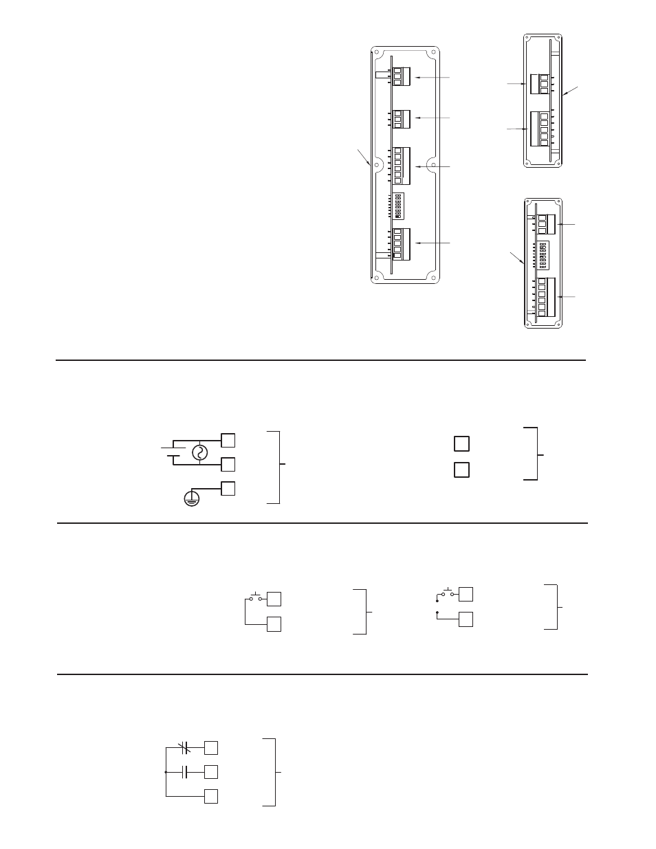
WIRING OVERVIEW
Electrical connections are made via pluggable terminal blocks located inside
the meter. All conductors should conform to the meter's voltage and current
ratings. All cabling should conform to appropriate standards of good installation,
local codes and regulations. It is recommended that the power supplied to the
meter (DC or AC) be protected by a fuse or circuit breaker. When wiring the
meter, compare the numbers on the label on the back of the meter case against
those shown in wiring drawings for proper wire position. Strip the wire, leaving
approximately 0.4" (10 mm) bare lead exposed (stranded wires should be tinned
with solder.) Insert the lead under the correct screw clamp terminal and tighten
until the wire is secure. (Pull wire to verify tightness.) Each terminal can accept
up to one #14 AWG (2.55 mm) wire, two #18 AWG (1.02 mm), or four #20
AWG (0.61 mm). Use copper conductors only, with insulation rated at 90°C.
WIRING CONNECTIONS
Internal removable terminal blocks are used for power and signal wiring.
Access to terminal blocks is through conduit fittings. Remove end plates with
¼" nut driver. For LD4 versions, all wiring is on right side of unit. For LD2
versions, power and input wiring connections are on the right side and the relay
and serial connections are on the left side.
DIP switch 6 OFF
DIP switch 6 ON
The power wiring is made via the 3 position terminal block (TBA) located
inside the unit (right side). The DC out power is located on TBB (right side).
3.1 POWER WIRING
COMM
+ EXC
6
4
TBB
DC Out Power
Terminal 4: + 24 VDC OUT
Terminal 6: User Common
Power
Terminal 1: VAC/DC +
Terminal 2: VAC/DC -
Terminal 3: Protective Conductor
Terminal
1
2
L1
L2
3
TBA
+
-
3.2 RESET/USER INPUT WIRING
The Reset/User Input is located on the right side
Terminal 5: Reset/User Input
Terminal 6: User Common
RESET/USER
5
COMM
6
TBB
RESET/USER
COMM
6
5
TBB
+
-
Sinking Logic
Sourcing Logic
Front
45
3
TBD
12
TBC
TBB
3
2
1
TBA
8
1
2
6
35
4
1
3
1
2
3
2
1
5
4
3
12
TBD
TBC
Front
TBB
Front
6
5
4
3
2
1
8
1
TBA
3
2
1
LD4
LD2 Right Side
LD2 Left Side