2 module 2 - d, Isplay, Ront – Red Lion LDSS User Manual
Page 6: Anel, Arameters
6
USER INPUT FUNCTION
PARITY BIT
METER ADDRESS
This parameter only appears when the Data Bit parameter is set to 7-bit. Set
the parity bit to match that of the host device. If parity is set to
, an additional
stop bit is used to force the frame size to 10 bits.
Enter the meter (node) address. With a single slave unit, an address is not
required and a value of zero should be used. This is the case with an RS232
connection, where only one Serial Slave is connected to the host.
With multiple Serial Slaves connected on an RS485 bus, a unique address
number must be assigned to each unit in order to send data to a specific slave
on the bus. If multiple slaves are assigned the same address (including zero),
common data can be sent to, and displayed by multiple slave units on the bus.
to
USER INPUT ASSIGNMENT
Select the display to which the User Input Function applies. The User Input
Assignment only appears if the secondary display is enabled and a selection of
reset or display hold is chosen for the User Input Function.
Assignment choices include the main (primary) and/or secondary display,
or the display which is shown at the moment the User Input is activated (
).
Note: For reset selection, main display resets to zero. Secondary display
resets to all blanks.
DATA RECEIVE DELAY TIME
Upon receiving a terminator character
data reception for the time duration entered in this parameter. Using a delay
allows the Serial Slave to ignore additional characters such as a
and hundredths of seconds format, with a 10 msec minimum delay time.
(See “Data Receive Delay Timing” in the Communications section for
additional timing details.)
to
User Input disabled.
See Programming Mode
Access chart (Module 2).
Momentary reset of the assigned
display(s).
Level active reset of the
assigned display(s).
Freeze the assigned display(s)
as long as the input is active.
Increase intensity one level for
each activation.
Toggle between main and
secondary display (if enabled).
DISPLAY
DESCRIPTION
No Function
Program Mode Lock-out
Momentary Reset
(Edge triggered)
Maintained Reset
Display Hold
Display Intensity Level
(Edge triggered)
Display Select
(Edge triggered)
MODE
Select
to allow the
SEL
key to toggle between the main and secondary
displays. This parameter only appears if the secondary display is enabled.
FRONT PANEL DISPLAY SELECT ENABLE (SEL
)
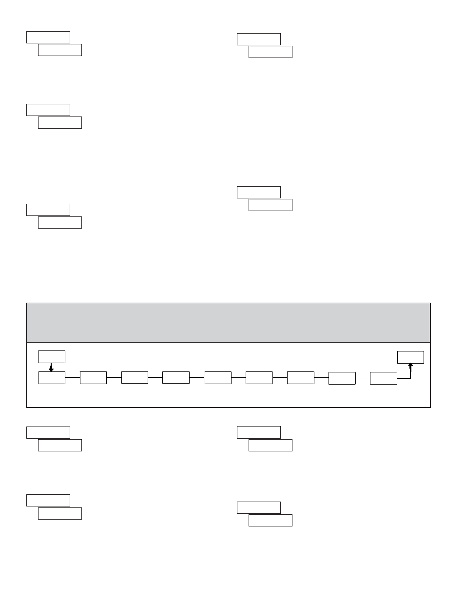
4.2 MODULE 2 - D
ISPLAY
AND
F
RONT
P
ANEL
K
EY
P
ARAMETERS
(
)
PAR
Front Panel
Display Select
Enable
Secondary
Display Enable
Display Scroll
Interval
Front Panel
Display Reset
Enable
E41
4&$&O
4&-&O
4DSP--
S4U&O
1SP
Display Reset
at Power-Up
S4U61
Display
Intensity Level
E-&7
Leading Zero
Display Enable
-&S0
$PE&
Programming
Security Code
Load Factory
Default Settings
'"$4&U
PARAMETER MENU
This parameter allows the
RST
key to reset the main (primary) and/or
secondary display (if enabled), or the display which is currently shown (
).
Select
to disable the
RST
key.
Note: Main display resets to zero. Secondary display resets to all blanks.
FRONT PANEL DISPLAY RESET ENABLE (RST
)
Select the time interval at which the display automatically toggles between
the main and secondary displays. Select
to disable automatic scrolling. This
parameter only appears if the secondary display is enabled.
DISPLAY SCROLL INTERVAL
Select
to enable the secondary display. A “2” on the far right of the display
always appears when the secondary display is shown.
SECONDARY DISPLAY ENABLE