Rogramming, Eter, 1 module 1 - i – Red Lion LDSS User Manual
Page 5: Nput, Etup, Arameters, E41 */1
Parameters
Input Setup
1SP
DISPLAY
MODE
Panel Key
Parameters
Display and Front
/0
PAR
SEL
PAR
PAR
E41
*/1
S
5
PROGRAMMING MODE ENTRY (PAR KEY)
It is recommended all programming changes be made off line, or before
installation. The meter normally operates in the Display Mode. No parameters
can be programmed in this mode. The Programming Mode is entered by
pressing the
PAR
key. If it is not accessible, then it is locked by either a security
code or a hardware lock (See Module 2).
MODULE ENTRY (SEL
& PAR KEYS)
The Programming Menu is organized into two modules. These modules group
together parameters that are related in function. The display will alternate between
and the present module. The
SEL
key is used to select the desired module.
The displayed module is entered by pressing the
PAR
key.
MODULE MENU (PAR KEY)
Each module has a separate module menu (which is shown at the start of each
module discussion). The
PAR
key is pressed to advance to a particular parameter
to be changed, without changing the programming of preceding parameters.
After completing a module, the display will return to
. Programming
may continue by accessing additional modules.
SELECTION / VALUE ENTRY
For each parameter, the display alternates between the present parameter and
the selections/value for that parameter. The
SEL
and RST
keys are used to
move through the selections/values for that parameter. Pressing the
PAR
key,
stores and activates the displayed selection/value. This also advances the meter
to the next parameter.
For numeric values, the value is displayed with one digit flashing (initially the
right most digit). Pressing the
RST
key increments the digit by one or the user
can hold the
RST
key and the digit will automatically scroll. The
SEL
key
will select the next digit to the left. Pressing the
PAR
key will enter the value and
move to the next parameter.
PROGRAMMING MODE EXIT (PAR KEY)
The Programming Mode is exited by pressing the
PAR
key with
displayed. This will commit any stored parameter changes to memory and return
the meter to the Display Mode. (If power loss occurs before returning to the
Display Mode, verify recent parameter changes.)
PROGRAMMING TIPS
It is recommended to start with Module 1 and proceed through each module in
sequence. When programming is complete, it is recommended to record the
parameter programming and lock out parameter programming with the user input
or programming security code.
FACTORY SETTINGS
Factory Settings may be completely restored in Module 2. This is useful when
encountering programming problems or in the event of corrupted program data.
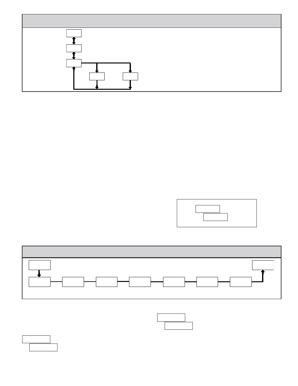
ALTERNATING SELECTION DISPLAY
In the explanation of the modules, the following dual display with arrows will
appear. This is used to illustrate the display alternating between the parameter
on top and the parameter’s Factory Setting on the bottom. In most cases,
selections and values for the parameter will be listed on the right.
4.0 P
ROGRAMMING
THE
M
ETER
PROGRAMMING MENU
Indicates Program Mode Alternating Display
Factory Settings are shown.
Parameter
Selection/Value
PAR
Data Bit
Baud Rate
Parity Bit
Meter
Address
**/1
C"6E
E"U"
1"SJU:
"EES
1SP
Data Receive
Delay Time
E&-":
User Input
Function
64S*/1
User Input
Assignment
64S"4/
4.1 MODULE 1 - I
NPUT
S
ETUP
P
ARAMETERS
(
)
PARAMETER MENU
Module 1 is the programming module for the Input Setup Parameters. This
includes the Serial Input setup parameters and the User Input function. Set the
Serial Input parameters to match the settings of the host device.
BAUD RATE
Set the baud rate to match that of the host device. Normally, the baud rate is
set to the highest value that all the serial communications equipment is capable
of transmitting and receiving.
DATA BIT
Select either 7- or 8-bit data word length to match that of the host device.