1 power wiring, 2 user input wiring, Wiring overview – Red Lion LDSS User Manual
Page 3
3
Front
2
2
35
4
TBD
1
6
45
3
TBB
TBA
1
3
1
2
LD4SS6P0 Right Side
LD2SS6P0 Right Side
LD2SS6P0 Left Side
The power wiring is made via the 3 position terminal block (TBA) located inside unit (right side).
2.1 POWER WIRING
AC Power
Terminal 1: VAC/DC +
Terminal 2: VAC/DC -
Terminal 3: Earth Ground
1
2
AC
AC
3
TBA
_
+
c. Connect the shield to common of the meter and leave the other end of the
shield unconnected and insulated from earth ground.
3. Never run Signal or Control cables in the same conduit or raceway with AC
power lines, conductors feeding motors, solenoids, SCR controls, and
heaters, etc. The cables should be ran in metal conduit that is properly
grounded. This is especially useful in applications where cable runs are long
and portable two-way radios are used in close proximity or if the installation
is near a commercial radio transmitter.
4. Signal or Control cables within an enclosure should be routed as far as possible
from contactors, control relays, transformers, and other noisy components.
5. In extremely high EMI environments, the use of external EMI suppression
devices, such as ferrite suppression cores, is effective. Install them on Signal
and Control cables as close to the unit as possible. Loop the cable through the
core several times or use multiple cores on each cable for additional protection.
Install line filters on the power input cable to the unit to suppress power line
interference. Install them near the power entry point of the enclosure. The
following EMI suppression devices (or equivalent) are recommended:
Ferrite Suppression Cores for signal and control cables:
Fair-Rite # 0443167251 (RLC# FCOR0000)
TDK # ZCAT3035-1330A
Steward # 28B2029-0A0
Line Filters for input power cables:
Schaffner # FN610-1/07 (RLC# LFIL0000)
Schaffner # FN670-1.8/07
Corcom # 1 VR3
Note: Reference manufacturer's instructions when installing a line filter.
6. Long cable runs are more susceptible to EMI pickup than short cable runs.
Therefore, keep cable runs as short as possible.
7. Switching of inductive loads produces high EMI. Use of snubbers across
inductive loads suppresses EMI.
Snubber: RLC# SNUB0000.
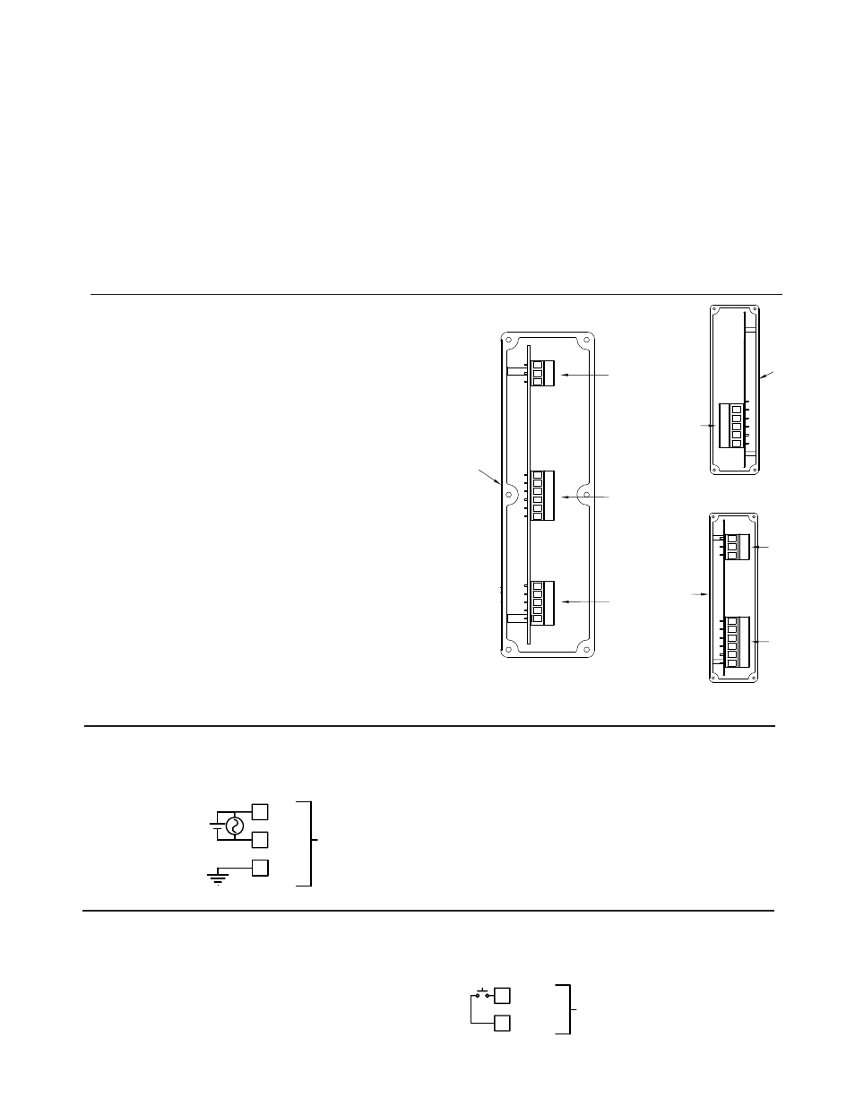
WIRING OVERVIEW
Electrical connections are made via pluggable terminal blocks located inside
the meter. All conductors should conform to the meter's voltage and current
ratings. All cabling should conform to appropriate standards of good installation,
local codes and regulations. It is recommended that the power supplied to the
meter (DC or AC) be protected by a fuse or circuit breaker. When wiring the
meter, compare the numbers on the label on the back of the meter case against
those shown in wiring drawings for proper wire position. Strip the wire, leaving
approximately 0.4" (10 mm) bare lead exposed (stranded wires should be tinned
with solder.) Insert the lead under the correct screw clamp terminal and tighten
until the wire is secure. (Pull wire to verify tightness.) Each terminal can accept
up to one #14 AWG (2.55 mm) wire, two #18 AWG (1.02 mm), or four #20
AWG (0.61 mm). Use copper conductors only, with insulation rated at 90°C.
2.2 USER INPUT WIRING
The User Input is wired to Terminals 5 and 6 of TBB as shown.
Terminal 5: User Input
Terminal 6: User Common
USER
5
COMM
6
TBB
Sinking Logic
5
4
3
12
TBD
Front
TBB
Front
6
5
4
3
2
1
TBA
3
2
1