Iring, Eter, Nstalling – Red Lion LDSS User Manual
Page 2
2
5. MEMORY: Nonvolatile E
2
PROM retains all programming parameters, main
and secondary displays when power is removed.
6. CERTIFICATIONS AND COMPLIANCES:
SAFETY
UL Listed, File # E137808, UL508, CSA C22.2 No. 14-M95
LISTED by Und. Lab. Inc. to U.S. and Canadian safety standards
Type 4X Enclosure rating (Face only), UL50
IEC 61010-1, EN 61010-1: Safety requirements for electrical equipment for
measurement, control, and laboratory use, Part 1.
IP65 Enclosure rating (Face only), IEC 529
ELECTROMAGNETIC COMPATIBILITY
Emissions and Immunity to EN 61326: Electrical Equipment for Measurement,
Control and Laboratory use.
Notes:
1. Criterion A: Normal operation within specified limits.
7. CONNECTIONS:
Internal removable terminal blocks used for power and signal wiring.
Remove end plates with ¼" nut driver.
For LD2 versions power is on the right side and serial wiring is on the left
side. For LD4 versions, all wiring is on the right side of the unit.
Wire Strip Length: 0.4" (10 mm)
Wire Gage: 24-12 AWG copper wire, 90°C rated insulation only
Torque: 5.3 inch-lbs (0.6 N-m) max
Cable Diameter: Outside diameter must be 0.181" (4.6 mm) to 0.312" (7.9
mm) to maintain NEMA 4 rating of cord grips.
8. ENVIRONMENTAL CONDITIONS:
Operating temperature: 0 to 65 °C
Storage temperature: -40 to 70 °C
Operating and storage humidity: 0 to 85% max. RH (non-condensing)
Vibration According to IEC 68-2-6: Operational 5 to 150 Hz, in X, Y, Z
direction for 1.5 hours, 2 g’s (1g relay).
Shock According to IEC 68-2-27: Operational 30 g’s (10g relay), 11 msec in
3 directions.
Altitude: Up to 2,000 meters
9. CONSTRUCTION: Aluminum enclosure, and steel side panels with
textured black polyurethane paint for scratch and corrosion resistance
protection. Sealed front panel meets NEMA 4X/IP65 specifications.
Installation Category II, Pollution Degree 2.
10. WEIGHT:
LD2SS6P0: 4.5 lbs (2.04 kg)
LD4SS6P0: 10.5 lbs (4.76 kg)
2.0 W
IRING
THE
M
ETER
EMC INSTALLATION GUIDELINES
Although this meter is designed with a high degree of immunity to Electro-
Magnetic Interference (EMI), proper installation and wiring methods must be
followed to ensure compatibility in each application. The type of the electrical
noise, source or coupling method into the meter may be different for various
installations. The meter becomes more immune to EMI with fewer I/O
connections. Cable length, routing, and shield termination are very important
and can mean the difference between a successful or troublesome installation.
Listed below are some EMC guidelines for successful installation in an
industrial environment.
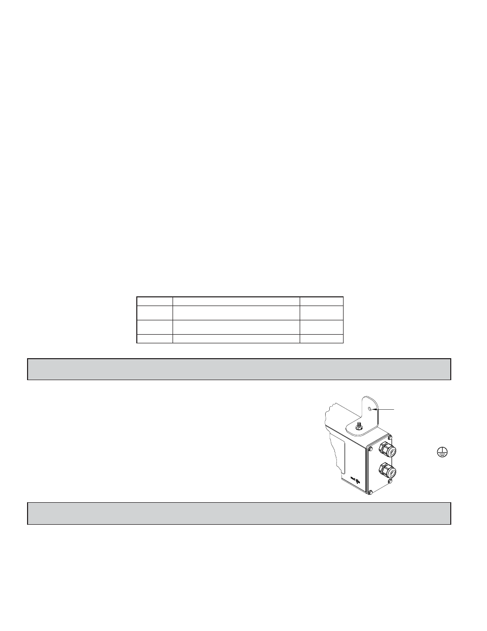
1. The meter should be properly connected to protective earth.
2. Use shielded (screened) cables for all Signal and Control inputs. The shield
(screen) pigtail connection should be made as short as possible. The
connection point for the shield depends somewhat upon the application.
Listed below are the recommended methods of connecting the shield, in order
of their effectiveness.
a. Connect the shield only at the panel where the unit is mounted to earth
ground (protective earth).
b. Connect the shield to earth ground at both ends of the cable, usually when
the noise source frequency is above 1 MHz.
Class B
EN 55011
Emissions
Emissions:
0.5 cycle
Criterion A
3 V/rms
Voltage dip/interruptions
Criterion A
EN 61000-4-6
RF conducted interference
1 kV L-L,
Criterion A
EN 61000-4-5
Surge
1 kV signal
2 kV power
Criterion A
EN 61000-4-4
Fast transients (burst)
2 kV L&N-E power
10 V/m
Criterion A
EN 61000-4-3
Electromagnetic RF fields
8 kV air discharge
4 kV contact discharge
Criterion A
EN 61000-4-2
Electrostatic discharge
Immunity to Industrial Locations:
ORDERING INFORMATION
LD Plug
LD
LD
MODEL NO.
DESCRIPTION
PART NUMBER
LD2SS6P0
LDPLUG00
LD4SS6P0
2.25" High 6-Digit Red LED Serial Slave Display,
RS232/RS485 Serial Communications
Panel Meter Plug for LD models
4" High 6-Digit Red LED Serial Slave Display,
RS232/RS485 Serial Communications
1.0 I
NSTALLING
THE
M
ETER
INSTALLATION
The meter meets NEMA 4X/IP65 requirements when properly installed.
INSTALLATION ENVIRONMENT
The unit should be installed in a location that does not exceed the operating
temperature. Placing the unit near devices that generate excessive heat should
be avoided. The unit should only be cleaned with a soft cloth and neutral soap
product. Do NOT use solvents.
Continuous exposure to direct sunlight may accelerate the aging process of
the front overlay. Do not use tools of any kind (screwdrivers, pens, pencils, etc.)
to operate the keypad of the unit.
MOUNTING INSTRUCTIONS
This display is designed to be
wall mounted or suspended
from a ceiling truss or other
suitable structure capable of
supporting the LDSS.
Caution should be exercised
when hanging the display to
provide for the safety of
personnel. If hanging the
LDSS, run the suspension
cables (or chains) through the
mounting bracket holes. For wall
mounting use #10-32 size bolts.
MOUNTING HOLE (.281")
MUST BE
CONNECTED TO
TERMINAL #3 (TBA)