Hardware – description and installation, 1 - host adapter descriptions and pcb layout, Rocketraid 2740 host adapter layout – HighPoint RocketRAID 2740 User Manual
Page 9
9
Hardware – Description and Installation
1 - Host Adapter Descriptions and PCB Layout
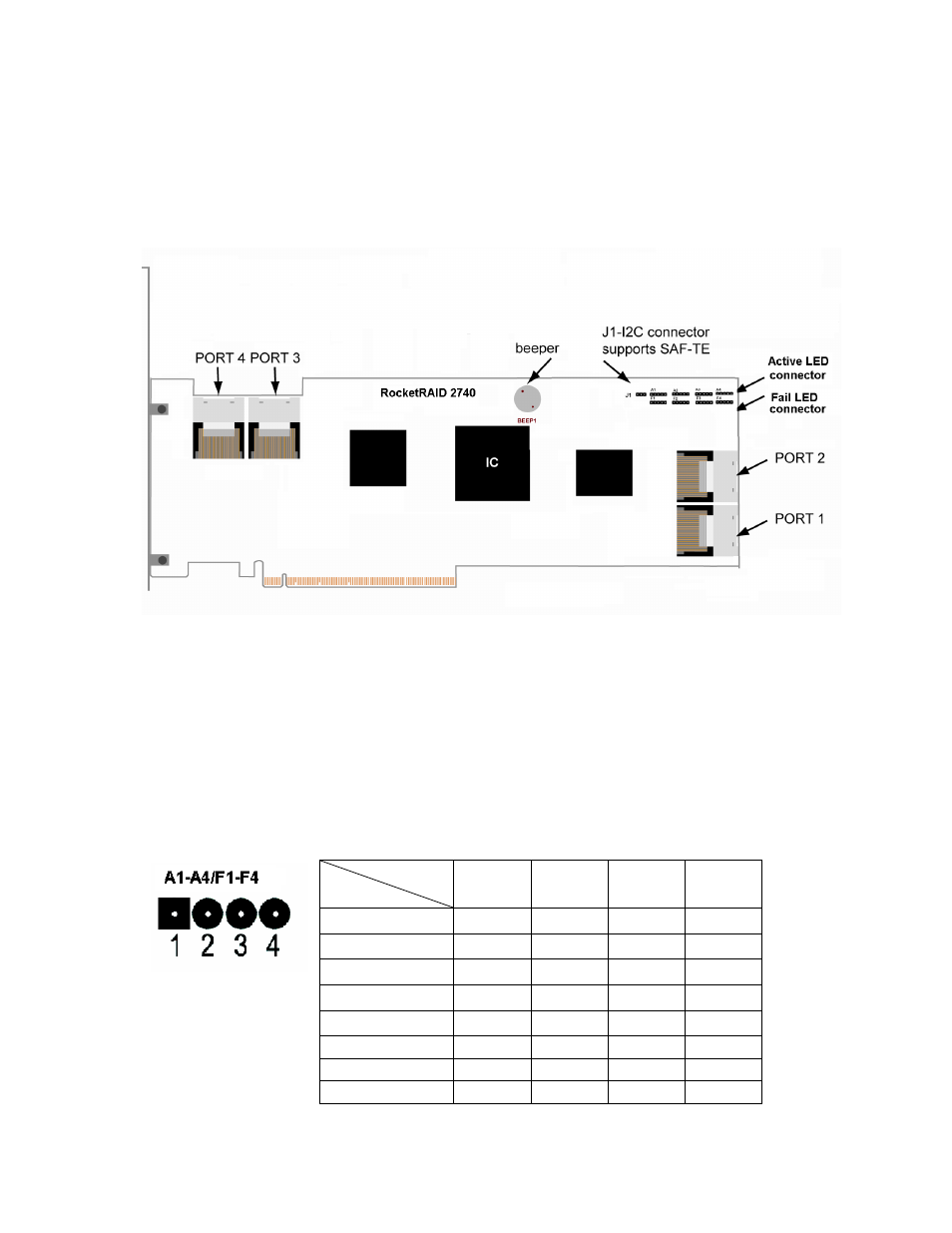
RocketRAID 2740 Host Adapter layout
Port1-Port4
These represent the RocketRAID 2740/2744’s four Internal Mini-SAS ports. Each port can support up
to 4 SATA/SAS hard disks.
LED Connections
LED connectors (Drive-activity/Drive-failure): The RocketRAID 2740/2744 host adapter has 16 LED
connectors that are used to indicate the activity and failure status of hard drives attached to the card’s 16
SATA/SAS channels.
A1-A4, F1-F4
A1-A4 provide LED support for Drive Activity, while F1-F4 supports Drive Failure.
Pin Connections represent SATA/SAS channel/port
Pin Number
Pin 1
Pin 2
Pin3
Pin4
A1
Channel 1
Channel 2
Channel 3
Channel 4
A2
Channel 5
Channel 6
Channel 7
Channel 8
A3
Channel 9
Channel 10
Channel 11
Channel 12
A4
Channel 13
Channel 14
Channel 15
Channel 16
F1
Channel 1
Channel 2
Channel 3
Channel 4
F2
Channel 5
Channel 6
Channel 7
Channel 8
F3
Channel 9
Channel 10
Channel 11
Channel 12
F4
Channel 13
Channel 14
Channel 15
Channel 16
Connections