DAVIS DriveRight Installation - OBD II (8156OBD, 8160OBD) User Manual
Page 9
7
Note: Test the vehicle chassis ground using a multimeter before connecting the ground
wire.
7. Use the in-line butt splices to connect the blue wires with fuses to the
Green (Digital Input 1) and Yellow (Digital Input 2) wires from the
adapter cable.
8. Connect Digital Input 1 to the desired circuit, typically the brake
light circuit.
9. Connect Digital Input 2 to the desired circuit, typically the headlight
circuit.
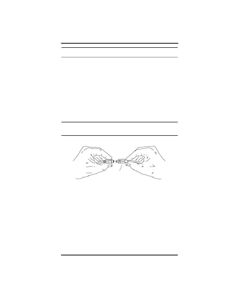
10.Connect the digital input cable to the OBD cable.
It is easiest to make the connection by first holding the OBD cable
connector by the housing. Then hold the adapter connector on the
cable itself next to the sliding connector housing and push the two
connectors together. The two cables will lock together when prop-
erly connected.
Note: To disconnect the cables, hold the both cables by the housing and pull apart. The
sliding housing on the adapter cable connector will release the lock and allow the
cables to be separated.
Sliding
Connector
Housing
Adapter Cable
OBD Cable
To Connect Cables,
Hold as Shown Here