Ridetech 11386799 User Manual
Page 7
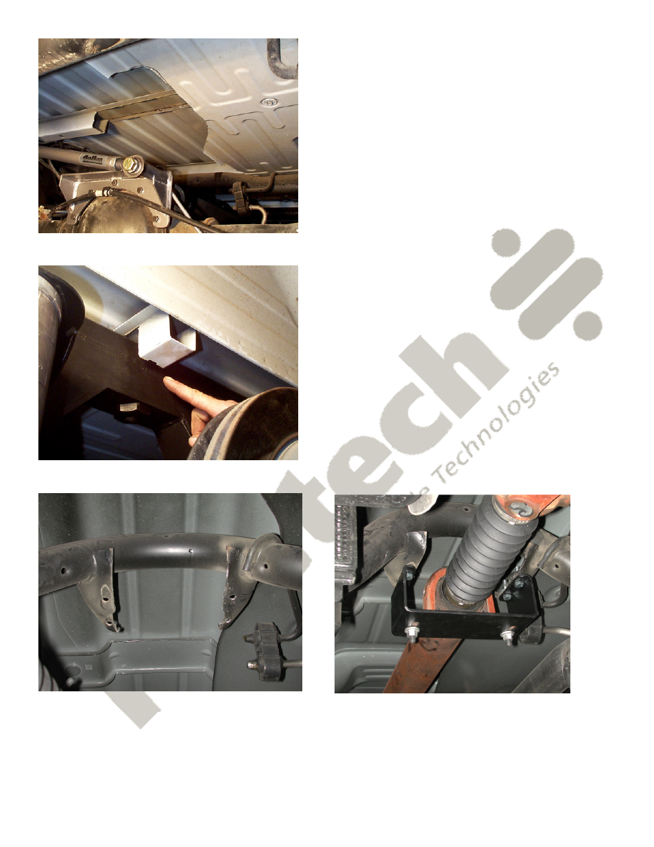
20. The driveshaft carrier bearing will need to be relocated to optimize driveline angles at your new
lower ride height. The oem carrier bearing bracket is sectioned as shown in the picture to the left.
The new carrier bearing bracket is then bolted onto the remaining tabs. The carrier bearing mount is
rotated 180 degrees and attached to the supplied bracket as shown in the picture on the right.
14. This photo shows how the bed brace and the
exhaust heat shield are trimmed for clearance. The
bed will need to be reinstalled to mark the exact
location of the cut.
15. The bed brace will also need to be trimmed
for clearance of the C notch reinforcement. A
cutoff wheel does a good job here.
See also other documents in the category Ridetech For the car:
- 13076799 (5 pages)
- 13056799 (5 pages)
- 13027199 (8 pages)
- 13017199 (7 pages)
- 13006799 (4 pages)
- 12226799 (5 pages)
- 12186799 (5 pages)
- 12176799 (7 pages)
- 12167199 (6 pages)
- 12087199 (8 pages)
- 11456799 (9 pages)
- 11446799 (6 pages)
- 11436799 (6 pages)
- 11406799 (5 pages)
- 11396799 (5 pages)
- 11376799 (6 pages)
- 11366799 (6 pages)
- 11267199 (7 pages)
- 11257199 (8 pages)
- 11177199 (8 pages)
- 11167199 (7 pages)
- 11167197 (7 pages)
- 11037199 (7 pages)
- 11027199 (7 pages)
- 19004901 (4 pages)
- 19004900 (4 pages)
- 19003005 (4 pages)
- 19003004 (4 pages)
- 19003003 (3 pages)
- 19003002 (4 pages)
- 19002005 (4 pages)
- 19002004 (4 pages)
- 19002003 (3 pages)
- 19002002 (4 pages)
- 12014099 (4 pages)
- 11014099 (4 pages)
- COIL-OVER Stud Top Assembly (1 page)
- COIL-OVER (2 pages)
- 12106509 (2 pages)
- 12103510 (4 pages)
- 12103509 (4 pages)
- 11326110 (6 pages)
- 11323510 (4 pages)
- 11323509 (4 pages)