Nitrous Express Hitman EFI User Manual
Page 3
solenoid brackets to the base of each solenoid. Do
not tighten! You may have to flip the mounting
bracket over to align the solenoid for the proper
orientation. Locate a suitable screw, bolt, or stud
to mount the solenoids. Choose a location that
allows the two nozzle feed lines some slack to
prevent any flow restrictions or influence on the
nozzle. Tighten all mounting screw and mount
locations securely now.
3. Thread the N2O (blue) steel braided line onto the
Nitrous solenoid outlet. Thread the Fuel (red) steel
braided line onto the Fuel solenoid outlet labeled
“Out” or “O”. Tighten securely.
4. The bottle-feed line will be attached to the N2O
Solenoid. See “Routing the Feed Line”. Before
you attach the nitrous supply line to the solenoid,
purge the line of any foreign matter that may have
accidentally entered the line during installation.
Do so by removing the tape used during installa-
tion and blowing compressed air through the feed
line. (Have an assistant hold the end of the hose
aimed away from the car and any people. Wear-
ing a glove is recommended). Immediately after
the purging operation, connect the main feed line
to the N2O solenoid and the nitrous bottle, secure
tightly.
BE SURE ALL NUTS ON SOLENOID MAGNETS
ARE TIGHT!
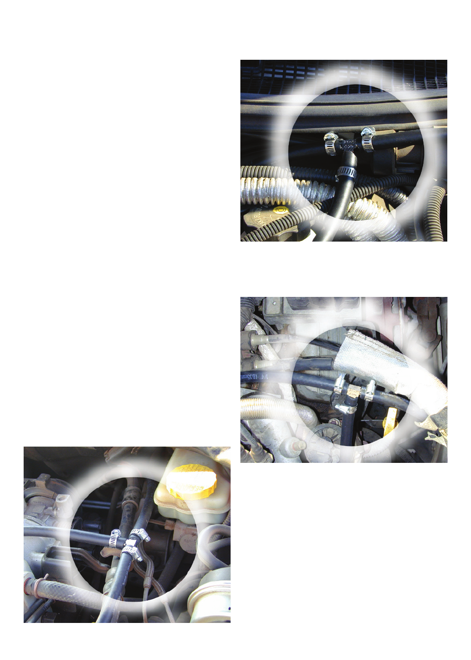
FUEL SUPPLY CONNECTION
To tap into the factory fuel delivery system. Splice
into the high-pressure rubber fuel line, between the
fuel filter and the injector fuel rail, and install the
furnished fuel tee. Use the supplied clamps, tighten
securely.
WARNING: The fuel rail and/or fuel lines are under
high pressure. Use extreme caution when disconnect-
ing any fuel line. Quickly collect and properly dispose
of any excess fuel spillage.
1. Connect one end of the main fuel feed line to the
fuel Tee connector and securely tighten.
2. Connect the other end of the fuel feed line to
the “IN” fitting of the fuel solenoid and securely
tighten the clamp.
ELECTRICAL HOOK-UP
1. Mount the toggle (Arming) switch in a location
that is within easy reach of the diver.
2. Using 14-ga. wire connect a switched HOT lead
(12 VDC POSITIVE) to the “Power” terminal of
the toggle switch. This power source must be con-